GE HEALTHCAREDRAFT VOLUSON E8 / VOLUSON E6
D
IRECTION KTD102576, REVISION 7 DRAFT (AUGUST 23, 2012) SERVICE MANUAL
Chapter 10 - Care & Maintenance 10-17
10-7-5 Chassis Leakage Current Test
10-7-5-1 Definition
This test measures the current that would flow through a grounded person who touches the accessible
conductive parts of the equipment during normal and fault conditions.
The test verifies the isolation of the power line from the chassis.
The meter is connected to parts of the equipment, easily contacted by the user or patient.
Measurements should be made under the test conditions specified in:
• Table 10-10 on page 10-13, or
• Table 10-11 on page 10-13, as applicable.
Record the highest reading.
10-7-5-2 Generic Procedure
The test verifies the isolation of the power line from the chassis.
The testing meter is connected from accessible metal parts of the case to ground.
Measurements should be made under the test conditions specified in:
• Table 10-10 on page 10-13, or:
• Table 10-11 on page 10-13, as applicable.
Record the highest reading of current.
When using the Microguard or a similar test instrument, its power plug may be inserted into the wall
outlet and the equipment under test is plugged into the receptacle on the panel of the meter.
This places the meter in the grounding conductor and the current flowing from the case to ground will
be indicated in any of the current ranges.
The maximum allowable limit for chassis source leakage is shown in:
• Table 10-10 on page 10-13, or
• Table 10-11 on page 10-13, as Chassis/Enclosure Leakage.
Follow the test conditions described for respective test points shown in Table 10-14.
!! DANGER:
Electric Shock Hazard.
When the meter's ground switch is OPEN, DO NOT not touch the system!
!! CAUTION:
Equipment damage possibility. Never switch the Polarity and the status of Neutral when the
system is powered ON. Be sure to turn the system power OFF before switching them using the
POLARITY switch and/or the NEUTRAL switch. Otherwise, the system may be damaged.
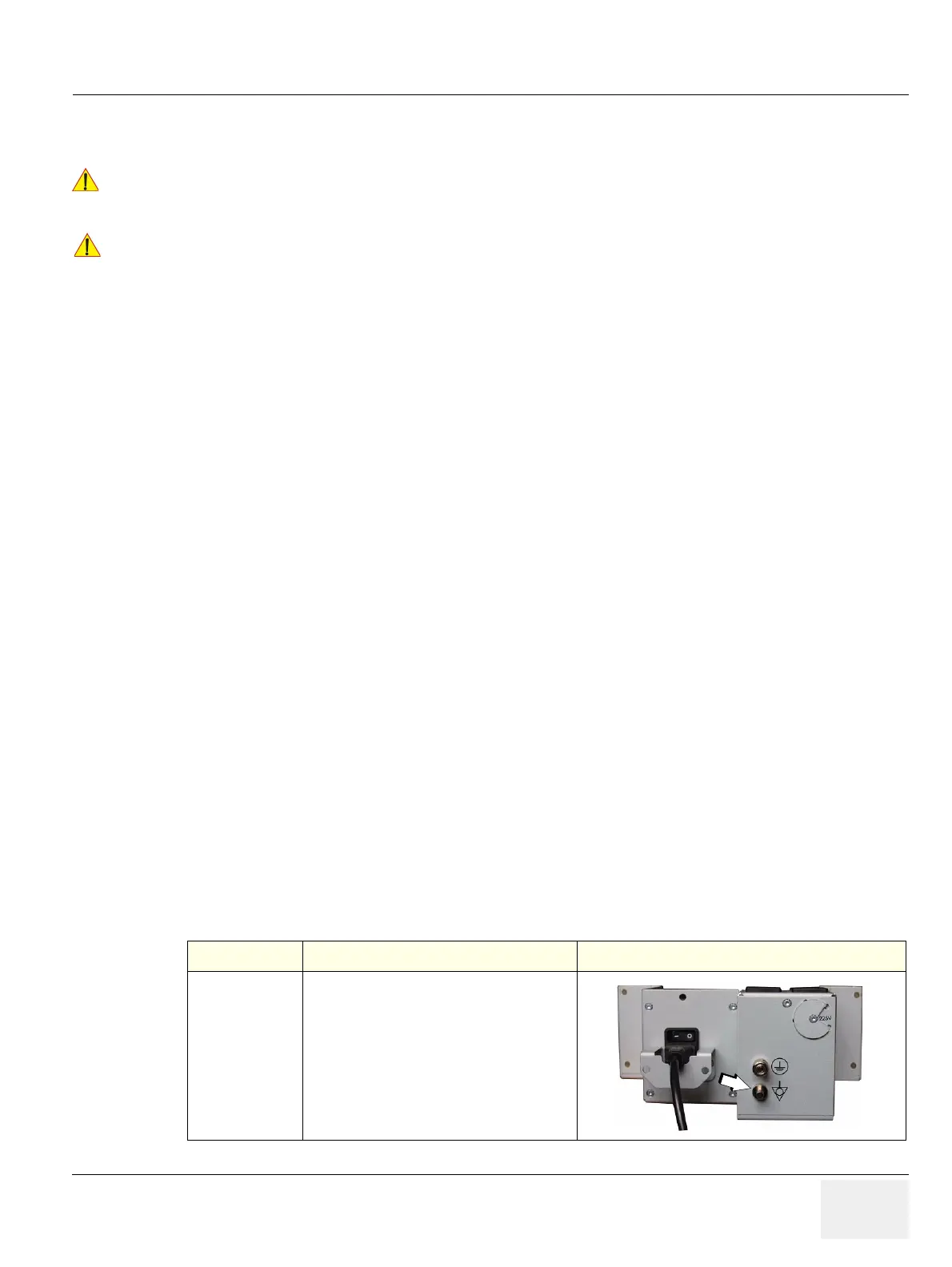
Table 10-14 Chassis Leakage Current Test Condition
TEST CONDITION TEST POINT (image)
1
Potential equilibrium connector
(rear of system, on primary power supply RTN)