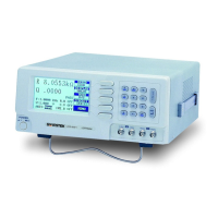
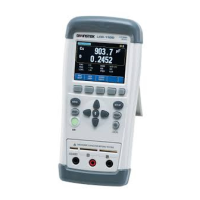
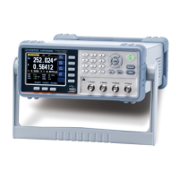
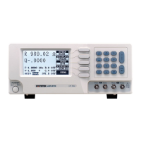
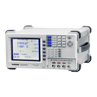
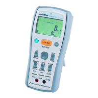
In the [MEAS SETUP] Page, you can configure each of
the following measurement controls with the cursor
placed in the corresponding field.
Measurement Function [FUNC]
*1
Impedance range [RANGE]
*1
Test Frequency [FREQ]
*1
Trigger Mode [TRIG]
*1
Test Signal Voltage Level [LEVEL]
*1
Measurement Speed [SPEED]
*1
Source Output Impedance [SRC RES]
Averaging Factor [AVG]
DC Bias Voltage [BIAS]
Auto LCZ Function [AUTO LCZ]
Monitor 1 and Monitor 2 Parameter Select [MON 1]
[MON 2]
Measurement Delay Time [DELAY]
Auto Level Control [ALC]
*1. These six settings can be set in the
[ MEAS DISPLAY] page and the [ BIN COUNT]
page. Please refer to section 4.1 [MEAS DISPLAY]
Page on page 24 for details.
5.1.1 Source Output Impedance [SRC RES]
The Source output impedance can be set to 30Ω, 50Ω or
100Ω.
If you use LCR-6000 Series to test a smaller inductor,
please use 30Ω.
If you need to compare test results with Keysight
E4980A, select 100Ω.
Procedure for setting source output impedance
Step 1. Press the [Setup] key.
Step 2. Use the cursor key to select the [SRC RES]
field.
Step 3. Use the soft-keys to set the source output
impedance.
All manuals and user guides at all-guides.com
all-guides.com
 Loading...
