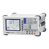
LCR-6000 Series User Manual
83
8.2 Connection
Electrical parameters
Interface power requirements: +12.4V~36VDC, 0.2A(Min).
Output circuit: Built-in pull-up resistors are internally connected to the
collector pin of the output transistors. The output pins are isolated by
photocouplers.
Input pins: Isolated by photocouplers.
Warning: To avoid damaging the interface,
ensure the external power does not exceed the
+12.4~36V input range.
To avoid damaging the interface, turn off the
meter before making any wired connections to
this interface.
If users need to use the output pins of this
interface to drive external relays, do use only
small signal relays. Because the output pins of
this interface are driven by photocouplers, the
fan-out current is not sufficient to drive big
relays; external transistors need to be used
when users want to use the signals on these
output pins to control big relays. The coil of
the external relays must be in parallel with a
flyback diode.

 Loading...