EasyManua.ls Logo

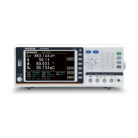
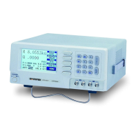
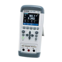
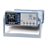
GW Instek LCR Series - Timing Chart for Handler Interface; Figure ‎ 8 -3 Circuit of Output Pins (bin Sorting, Index, EOM); Figure ‎ 8 -4 Timing Chart; Table 8-4 Timing Definitions

GW Instek LCR Series
143 pages
To Next Page IconTo Next Page
To Previous Page IconTo Previous Page
Loading...
Handler Interface
84
Circuit of output pins
Figure 8-3 Circuit of output pins (Bin sorting, Index, EOM)
Maximum sourcing current: 5mA.
Maximum sinking current: 50mA
8.3 Timing Chart for Handler Interface
Figure 8-4 Timing chart
Table 8-4 Timing Definitions
Time segment
Minimum
value
T1
Trigger pulse width
1msec
T2
Measurement
circle
Trigger delay time
< 10usec
T3
Analog Measurement
time
Depends on
settings
T4
Digital math time
1msec
T5
Bin output delay time
200usec
T6
Trigger wait time after the output
0sec
1
2
4
3
R 4.99k
EXT.DCV
OUTPUT
GND
All manuals and user guides at all-guides.com

Table of Contents

Other manuals for GW Instek LCR Series

Related product manuals