420
OPTIONS
96-8000
June 1999
7. In MDI mode, command an M17. The table will unclamp (raise) and the automatic door will open.
The door and table will stay up. Clean all shipping protectant from the rollers, alignment pins and
clamp bars.
8. In MDI mode, command an M14. The table will move to the pallet #1 load position. (The front right
corner of the VMC).
Note: M14 will move the table slowly in case a pallet is present.
9. Raise the APC with the forklift and install the leveling screws into the legs. As a preliminary height
setting, turn the screws until the length of screw extending above the APC leg is the same as the
length of VMC leveling screw extending above the VMC base. Set the leveling pads (3) in place.
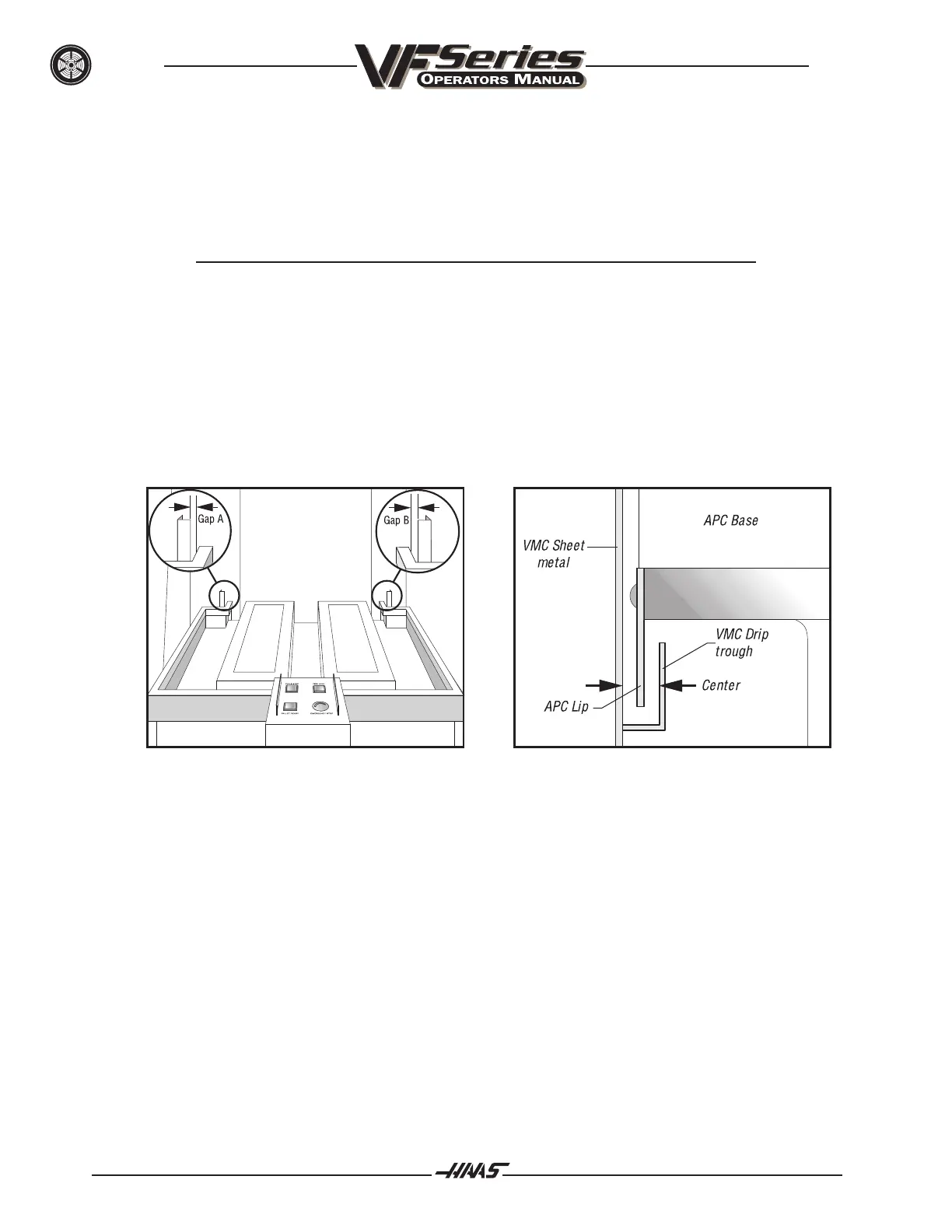
10. Set the APC in place on the leveling pads, so that it is centered in the VMC door opening (see
Figure 11.18). Ensure that the lip of the APC enclosure is centered in the VMC drip trough (see
Figure 11.19).
Figure 11.18 Gaps A and B should be equal. Figure 11.19 The APC lip should be centered
in the VMC drip trough.
11. Attach the APC brace to the VMC and the APC with six screws (four 3/8" screws in the APC legs
and two 1" screws in the VMC base), but DO NOT TIGHTEN (see Figure 11.20). The VF-3 uses
the two holes in the brace that are closest to the VMC, while the VF-4 uses the two holes farthest
from the VMC.

 Loading...


