EasyManuals Logo

Haas VF Series Operator's Manual

Haas VF Series
564 pages
To Next Page IconTo Next Page
To Previous Page IconTo Previous Page
Page #421 background imageLoading...
Page #421 background image
96-8000 421
OPTIONS
June 1999
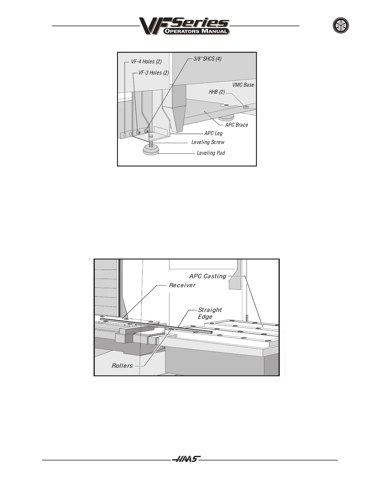
Figure 11.20 Installing the APC brace (VF-3 shown).
12. Place the straight-edge on top of the rollers of both the VMC receiver (unclamped) and the APC, to
check the APC height (see Figure 11.21). Make sure that at least 12" of the straight-edge is on
each in order to get an accurate reading. Adjust the leveling screws in the APC legs until the
straight-edge lays completely flat on all rollers.
Figure 11.21 APC roller alignment setup.
13. Place the straight-edge against the side of the rollers on the VMC receiver and the APC, to ensure
that the rollers are aligned in the Y-axis. The straight-edge must extend past at least two rollers on
both the APC and VMC to get an accurate reading.

Table of Contents

Other manuals for Haas VF Series

Questions and Answers:

Question and Answer IconNeed help?

Do you have a question about the Haas VF Series and is the answer not in the manual?

Haas VF Series Specifications

General IconGeneral
Machine TypeVertical Machining Center
ControlHaas CNC Control
Z-Axis Travel20-30 inches (varies by model)
Y-Axis Travel16 - 30 inches (varies by model)
Spindle Motor20-30 hp (depending on model)
Tool Capacity20-40 tools (varies by model)

Related product manuals