Creating the Digital Image 89
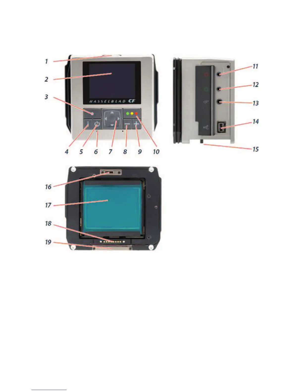
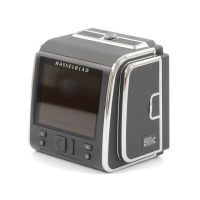
Figure 5-2 CF digital back operating controls. (1) Ventilator to keep unit cool, which must be
kept open; (2) preview screen; (3) Menu (Exit button) used for various functions; (4) display
button goes through various view modes; (5) ON/OFF button powers the digital back;
(6) Ready Light indicator fl ashes green when digital back is performing a task; (7) Navigation
button, a four-way rocker switch to step through preview images and navigate the Menu
system; (8) Zoom out button also allows you to see several small images; (9) Zoom in button
makes preview image larger; (10) Instant Approval (OK button); (11) Flash sync terminal;
(12) Camera communication port used only with certain cameras and described in adapter
user manual; (13) Flash out sync controls, 11 and 13 only used with studio fl ash; (14) FireWire
connector; (15) digital back retaining hook slots; (16) CCD and IR fi lter; (17) Databus
connectors; (18) digital back support slots; and (19) CF card slot cover.