Projecting Medium-Format Images 405
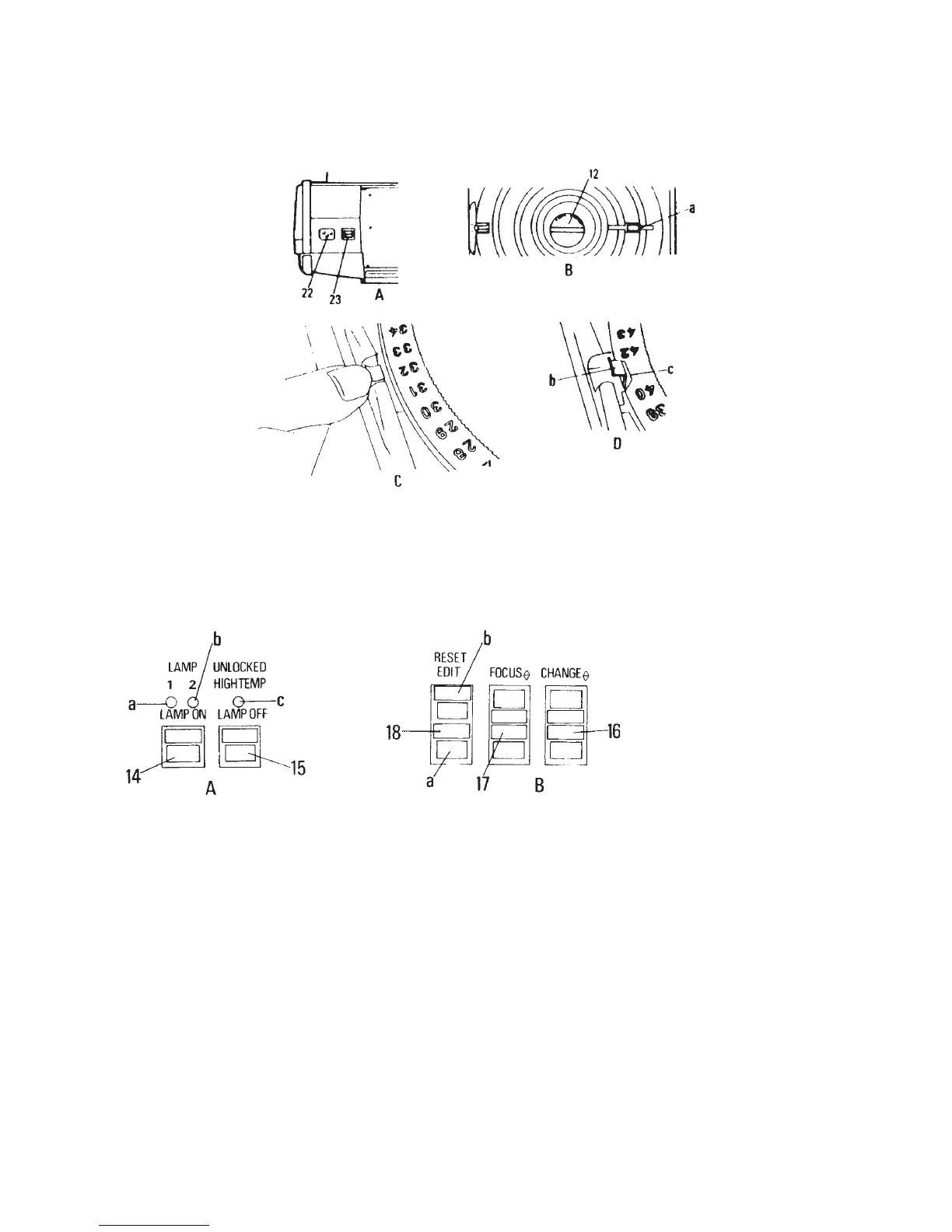
Figure 21-5 Starting the projection. (A) The power cable is connected to the socket (22). The fan
is turned on with the power switch (23). (B) Slide trays can be attached only when the tray
lock (12) is in the unlocked position, with the red control lamp burning. The slide-changing
arm (a) is then in the up position. If the lock cannot be moved to Unlock, press the Edit button
to bring the arm up. (D) Attach the slide tray so that its groove (c) engages in the sensor (b) for
the 0 position. (C) To attach the tray in any position other than 0, move the sensor outward.
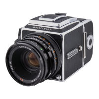
Figure 21-6 Operating controls. (A) The left side control panel has the lamp ON (14) and OFF
(15) switches. When lamp 1 is on, the green light (a) is lit. If the yellow lamp (b) is also lit,
projection lamp 2 is on, meaning that lamp 1 is burned out. If only the yellow indicating lamp
(b) is lit, the projection lamps have been interchanged, but lamp 2 is not lit, or both lamps
are burned out. The red lamp (c) is lit either when the magazine lock is not securely locked
or when the projector has overheated. (B) On the right control panel are the forward and
reverse slide-changing switches (16). Move the lens forward or backward to focus by pressing
the front or rear position of the switch (17). Pressing the rear (a) of the switch (18) moves the
slide back into the tray without advancing the tray. Pressing the top portion (b) turns off the
projection lamp and moves the tray to the fi rst position, where it stops.