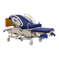
4.25 Patient Siderail (Inboard) P.C. Switch Board
Chapter 4: Procedures
Affinity® Four Birthing Bed Service Manual (195826 REV 2) 4 - 43
4
REMOVAL
1. Set the brake/steer pedal to the brake position.
2. Make sure the bed is out of the Trend-Like position.
3. Raise the head section to the high position.
4. Raise the bed to the high position.
Failure to unplug the bed could cause injury or equipment damage.
5. Unplug the bed from its power source.
6. Put the siderail lockout switch at the head end of the bed in the locked position.
7. Remove the eight plastic screws (A) that attach the patient siderail cover (B) to the siderail assembly
(C) (see
Figure 4-29 on page 4-44).
8. Carefully remove the patient siderail cover (B) from the siderail assembly (C).
9. Make a note of the wires and cable assembly routings and connections to make sure that they are
installed correctly during the replacement procedure.
10. Remove the four screws (D) that attach the P.C. switch board (E) to the patient siderail cover (B).
11. Slide the P.C. switch board (E) off the patient siderail cover (B) tabs, and remove the board from the
patient siderail cover (B).
12. Disconnect the two SideCom® Communication System cable assemblies (F) from the P.C. switch
board (E).
REPLACEMENT
1. Do the removal procedure in reverse order.
2. Do the “Function Checks” on page 2-5.