4.24 Siderail Assembly
Chapter 4: Procedures
Affinity® Four Birthing Bed Service Manual (195826 REV 2) 4 - 41
4
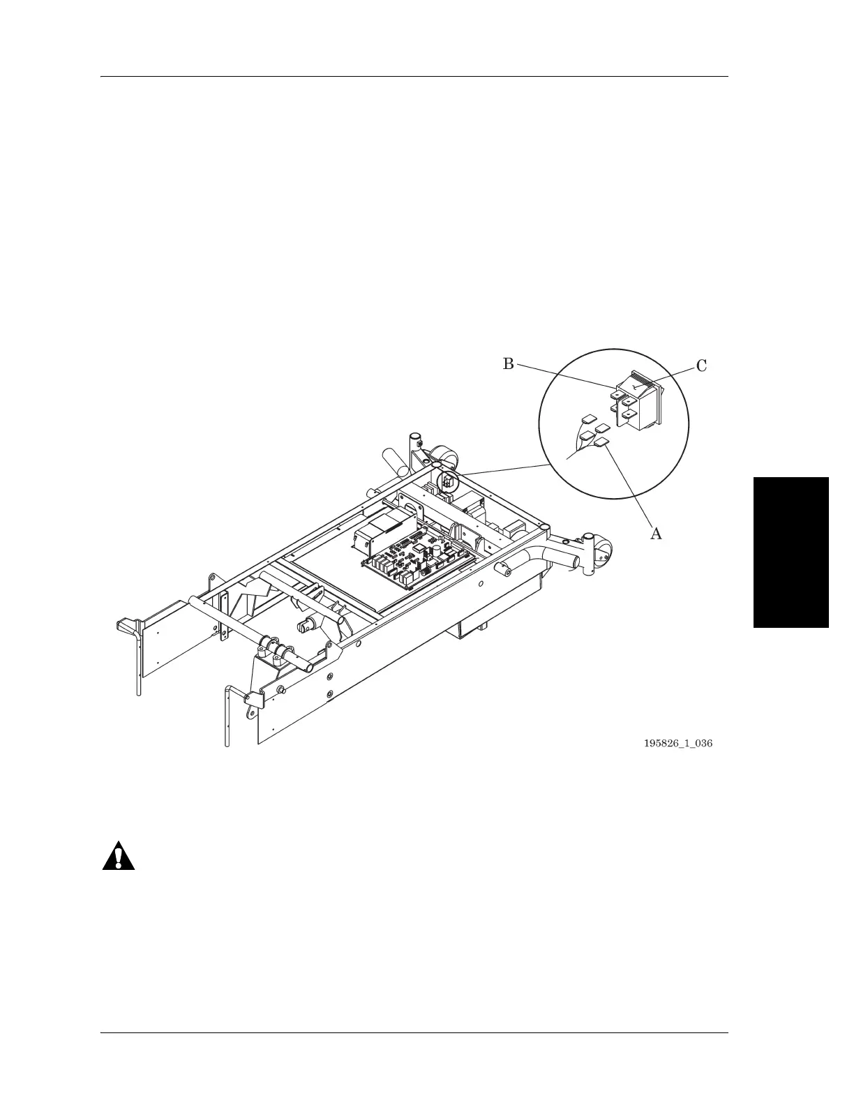
8. Identify and disconnect the wiring connector (A) from the lockout switch assembly (B) (see Figure 4-
27 on page 4-41).
9. Compress the tabs (C) on the lockout switch assembly (B).
10. Remove the lockout switch assembly (B) from the bed.
REPLACEMENT
1. Do the removal procedure in reverse order.
2. Make sure the wiring connector (A) is firmly connected to the lockout switch assembly (B).
3. Do the “Function Checks” on page 2-5.
Figure 4-27. Lockout Switch Assembly
4.24 Siderail Assembly
Tools: Small screwdriver Ratchet Needle nose pliers
7/16” socket
Follow all electrical safety precautions when servicing the bed’s electrical system. Failure to do so could
cause personal injury or equipment damage.
REMOVAL
1. Set the brake/steer pedal to the brake position.
2. Make sure the bed is out of the Trend-Like position.
3. Raise the head section to the high position.