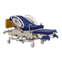
4.31 Central Braking System
Chapter 4: Procedures
Affinity® Four Birthing Bed Service Manual (195826 REV 2) 4 - 53
4
8. If the brake still does not hold, examine the caster (C) tire for wax buildup. Clean the tire with
turpentine if necessary.
9. Set the brake/steer pedal to the steer position.
10. Turn the brake/steer caster (C). The caster (C) should lock into a position parallel with the length of
the bed.
11. Set the brake/steer pedal to the neutral position.
12. Turn the brake/steer caster (C) 180°. The caster should again lock into a position parallel to the
length of the bed.
13. Set the brake/steer pedal to the in neutral position.
14. Turn the brake/steer caster (C) from side to side, and listen for a ratcheting sound.
15. If necessary, loosen the setscrew (D) to permit the caster (C) to turn without ratcheting, but so that it
can still be locked in the steer position.
BRAKE CASTER ADJUSTMENT
1. Do Step 1 through Step 8 of “Brake and Steer Caster Adjustment” on page 4-52.
4.31 Central Braking System
Tools: Phillips head screwdriver 1/8” drift punch 7/16” wrench
Blue Loctite® #242 Hammer ½” wrench
E-ring removal tool Anti-seize compound Needle nose pliers
Marker pen Small screwdriver T25 Torx® screwdriver
Red Loctite® #262 (2) pieces of 2" x 4" x 36" lumber
The brake/steer caster is at the left foot end of the base frame. The other three casters are brake casters.
To service the central braking system mechanism, lay the bed on its side. Before you do this, you must
disable the siderail and remove the brake/steer pedal.
REMOVAL
1. Determine which side the bed will be put on.
2. Disable the siderail: lower it beneath the bed and tie it in this position, or remove it as an assembly
from the bed (see
Procedure 4.24 on page 4-41).
3. Set the brake/steer pedal (A) to the steer position (see Figure 4-35 on page 4-54).
4. Remove the two screws (B) that attach the leg covers (C) to the bed (D).
5. Remove the leg covers (C).
6. Remove the foot-end rocker arm (E) as follows:
a. Remove the E-ring (F) from one side of the groove pin (G) that holds the rocker arm (E) above
the caster.
b. Remove the groove pin (G) to free the rocker arm (E).
c. Remove the spacers (H) on each side of the rocker arm (E).
d. Remove the hairpin (I) and connector pin (J) that attaches the metal brake strip (K) to the rocker
arm (E).
e. Lift out and remove the rocker arm (E).
7. Repeat Step 6 for the head-end rocker arm.
8. Set the brake/steer pedal (A) to the neutral position.