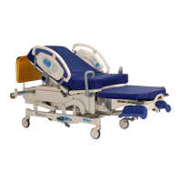
4.6 Head Drive Motor Assembly
Chapter 4: Procedures
4 - 12 Affinity® Four Birthing Bed Service Manual (195826 REV 2)
4.6 Head Drive Motor Assembly
Tools: T25 Torx® head bit Ratchet Needle nose pliers
Small wire cutters Warehouse safety stand kit (M01976) or equivalent
REMOVAL
1. Set the brake/steer pedal to the brake position.
2. Raise the bed to the high position.
3. Raise the head section to the high position.
Failure to unplug the bed could cause injury or equipment damage.
4. Unplug the bed from its power source.
5. Put the siderail lockout switch at the head end of the bed in the locked position.
6. Remove the top motor cover (see Procedure 4.1 on page 4-3).
7. Remove the bottom motor cover (see Procedure 4.2 on page 4-4).
Do not work under an unsupported load. Make sure to install the jack stands or suitably support the
bed. Personal injury can occur.
8. Support the bed with the warehouse safety stand kit (or equivalent).
Make sure the night light is not damaged when the bed is being lowered. Failure to do so could cause
equipment damage.
9. Remove the four screws (A) that attach the electronics plate weldment (B) to the bed frame (see
Figure 4-7 on page 4-13).
10. To improve access to the head drive motor assembly (C), carefully lift and move the electronics plate
weldment (B) to the patient’s left side of the bed.
11. Unplug the power cable (C) from logic control P.C. board connector P4.
12. Disconnect the CPR actuator from the head motor as follows:
a. Remove the two screws (D) that attach the cover (E) to the motor (F).
b. Slide the cover (E) down.
c. Remove the cable attachment (G) from the mount (H).
d. Remove the cable assembly (I) from the mount (H).
Support the head section before removing the cotter pins and clevis pins. Failure to do so could cause
personal injury or equipment damage.
13. Lift the head section frame (J) upward, and support it.
14. Remove the cotter pins (K) from the two clevis pins (L) that attach the head drive motor assembly (E)
to the bed frame.