4.4 Hilow Drive Motor Assembly
Chapter 4: Procedures
Affinity® Four Birthing Bed Service Manual (195826 REV 2) 4 - 7
4
Make sure the night light is not damaged when the bed is being lowered. Failure to do so could cause
equipment damage.
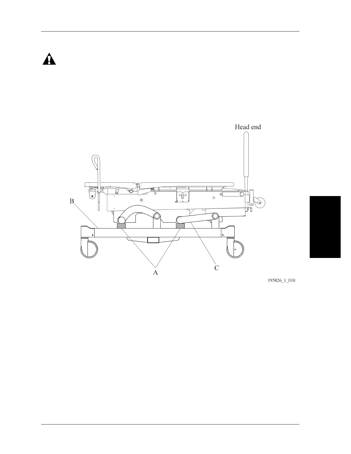
10. Put the lockout switch in the unlocked position, and lower the bed (B) until both lift arms (C) rest on
the warehouse safety stand.
Figure 4-4. Bed Support Location
11. Remove the four screws (D) that attach the electronics plate weldment (E) to the bed frame (see
Figure 4-5 on page 4-8).
12. To improve access to the hilow drive motor assembly (F) on the right side, carefully lift and move the
electronics plate weldment (E) to the patient’s left side of the bed.
13. Unplug the hilow drive motor assembly (F) power cable (G) from logic control P.C. board (H)
connector P15.
14. Remove two cotter pins (I) from the two clevis pins (J) that attach the hilow drive motor assembly
(F) to the bed frame.
15. Remove the two clevis pins (J) from the hilow drive motor assembly (F) and from the bed frame.
There is a bushing around the clevis pins.
16. Remove the hilow drive motor assembly (F).
REPLACEMENT
1. Do the removal procedure in reverse order.