4.9 Foot Drive Motor Assembly
Chapter 4: Procedures
4 - 18 Affinity® Four Birthing Bed Service Manual (195826 REV 2)
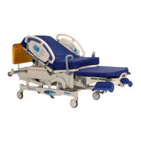
Figure 4-10. Foot Drive Motor Assembly
11. To improve access to the foot drive motor assembly (C) on the left side, carefully lift and move the
electronics plate weldment (B) to the patient’s right-hand side of the bed.
12. Disconnect the foot drive motor assembly (C) power cable (D) from P6 on the logic control
P. C .
board.
13. Remove the two cotter pins (E) from the two clevis pins (F) that attach the foot drive motor
assembly (C) to the bed frame.
14. Remove the two clevis pins (F) from the foot drive motor assembly (C), and from the bed frame.
There are bushings around the clevis pins.
15. Remove the foot drive motor assembly (C).
REPLACEMENT
1. Do the removal procedure in reverse order.
2. Do the “Foot Limit Switch Adjustment” on page 4-19.
3. Do the “Function Checks” on page 2-5.