Tabletop electric components
4990851_002_00 – 2082262 – 2022-01-10 45
b) The gap between the sensor and hinge must be 0.3 mm to
0.5 mm. Position the sensor accordingly.
12. Switch off the operating table using the switch at the running
gear.
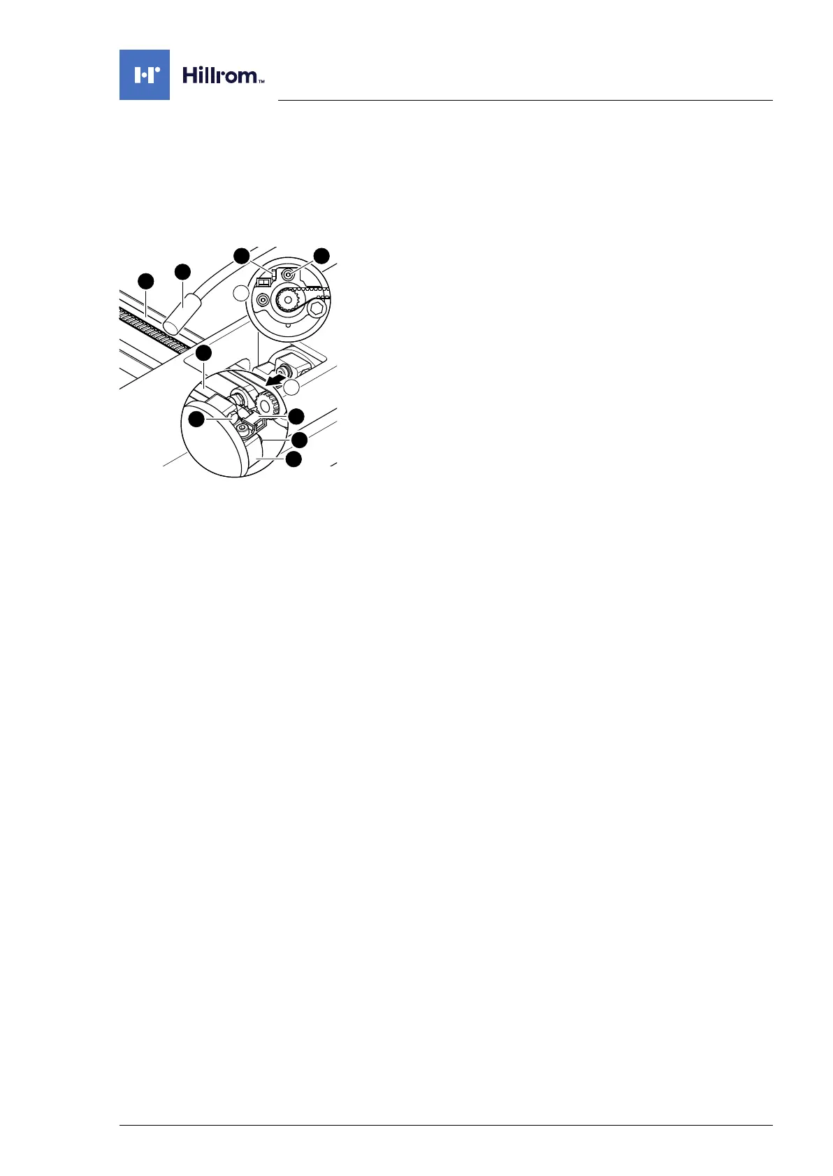
13. Suspend the cogged belt.
Ensure that the cogged belt is properly guided over the
clamp roller. The cogged belts must run parallel.
14. Adjust the cogged belt.
Evenly tension the cogged belt [1] on both sides.
a) Screw in the tensioning screw [3] on both clamping
devices [4].
b) Determine the cogged belt oscillation frequency using a
tension meter device [17] and readjust the cogged belt
tension where necessary using the tensioning screws [3]
(pre-tensioning 49 Hz ± 3 Hz, check 3x in succession).
c) Mount the clamping device [4] for the belts onto both
drive units for the leg section hinge (2 screws [18]).
15. Attach the cable clip [2] onto the drive unit (1 screw).
16. Apply new self-adhesive protective sheets to each of the
openings on both struts.
17. Mount the pad plate onto the strut (Chapter 7.2).
18. Put the pad in place.
19. Connect the power supply to the operating table
(Chapter 6.2).
20. Update the firmware of the operating table.