Tabletop electric components
4990851_002_00 – 2082262 – 2022-01-10 51
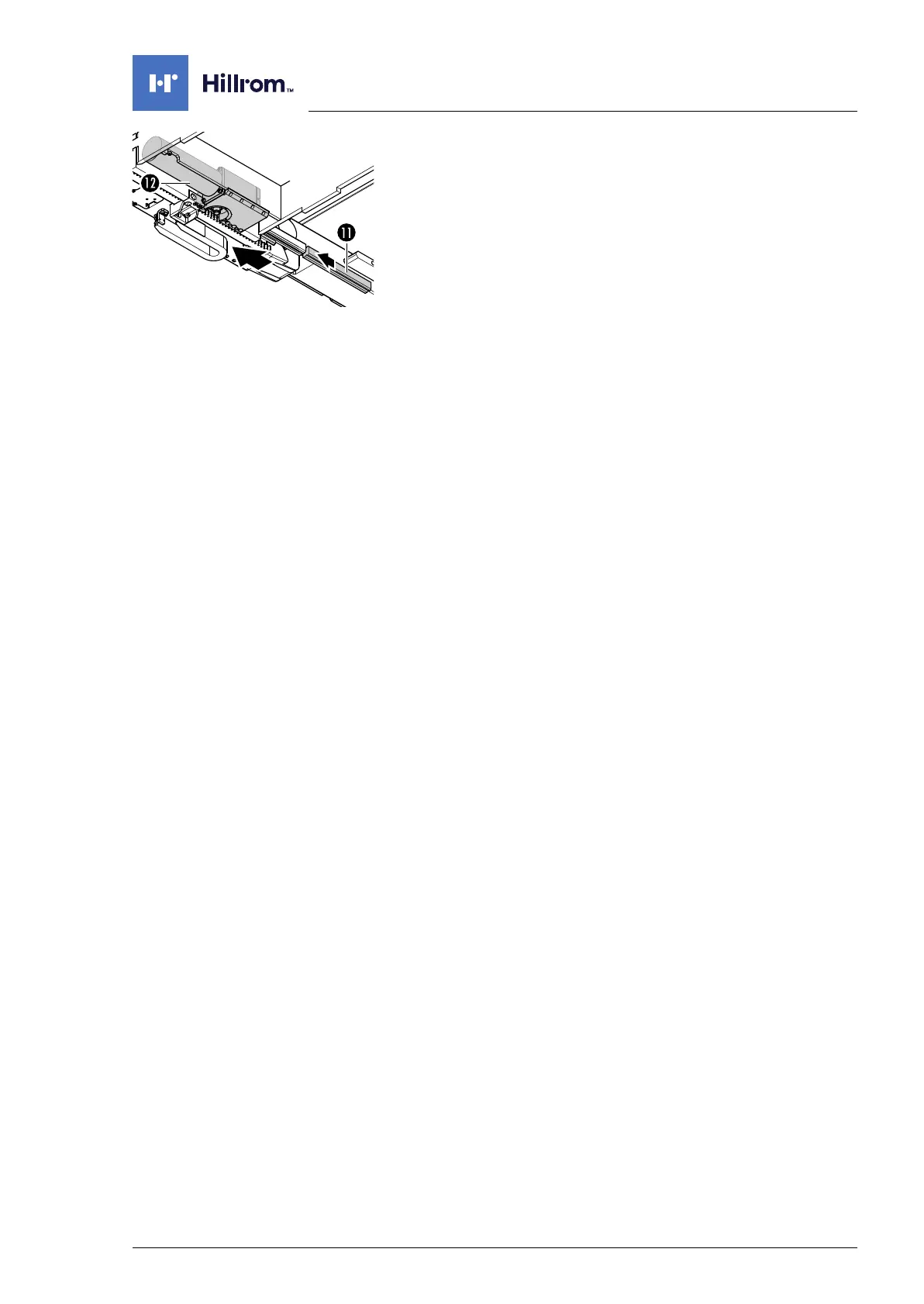
18. Slowly move the longitudinal slide of the tabletop manually in
the direction of the foot end. At the same time, the dummy
linear guides on both sides (#2067885) [11] must be inserted
as soon as the guide rail of the linear guide releases the
running groove of the track carriage.
Slowly continue to move the longitudinal slide of the tabletop
manually until the drive can be removed.
19. Hold the longitudinal slide motor tight and remove the drive
unit of the longitudinal slide [12] towards the bottom.
Assembly 1. Insert the drive unit longitudinal slide from the bottom into
the tabletop.
2. Slowly move the longitudinal slide of the tabletop manually in
the direction of the head end. The dummy linear guides must
be removed from both ends at the same time.
While moving the slide, ensure that the guide rail of the linear
guide correctly engages with the running groove of the track
carriage.
3. Return the power chain to its original mounting position.
Mount the power chain on the right at the foot end at the
tabletop (3 screws).
4. Return the power chain to its original mounting position.
Mount the power chain on the left at the foot end of the end
and reference switch from the tabletop (3 screws).
5. Engage and mount (4 screws each) the covers of the power
chain on both sides of the tabletop.
6. Mount the end stops on the column head on both sides of the
head end of the tabletop (2 screws each).
7. Mount the longitudinal slide drive unit on the column head (8
screws and 2 pins).
8. Switch on the operating table using the switch at the running
gear.
9. Shift the longitudinal slide of the tabletop to the head end
position.
10. Switch off the operating table using the switch at the running
gear.
11. Insert the gear wheel and mount (1 nut).
12. Mount the gear wheel cover (3 screws).
13. Restore the original cable routing. Mount the cable fastening
on the connecting cable drive unit longitudinal slide.
14. Attention: Do not interchange the plug connections. Pay
attention to the wiring diagram on page 64.
Restore the original cable routing. Insert the plug of
connecting cable into the W305 cable bushing.
15. Guide the column cover upwards and close (Chapter 6.6).
16. Mount the column head cover (Chapter 9.3).
17. Mount the pad plate onto the strut (Chapter 7.2).
18. Put the pad in place.
19. Connect the power supply to the operating table
(Chapter 6.2).
20. Update the firmware of the operating table.




 To Next Page