7.2 Event Detection Method
119
Frequency
Detection method:
Reciprocal detection (sampling at 2 MHz) with measurement and detection approximately every 200
ms (about once every 10 cycles at 50 Hz, every 12 cycles at 60 Hz, or every 80 cycls at 400 Hz)
The measurement source is U1, U2, or U3 (same as the PLL synchronization source)
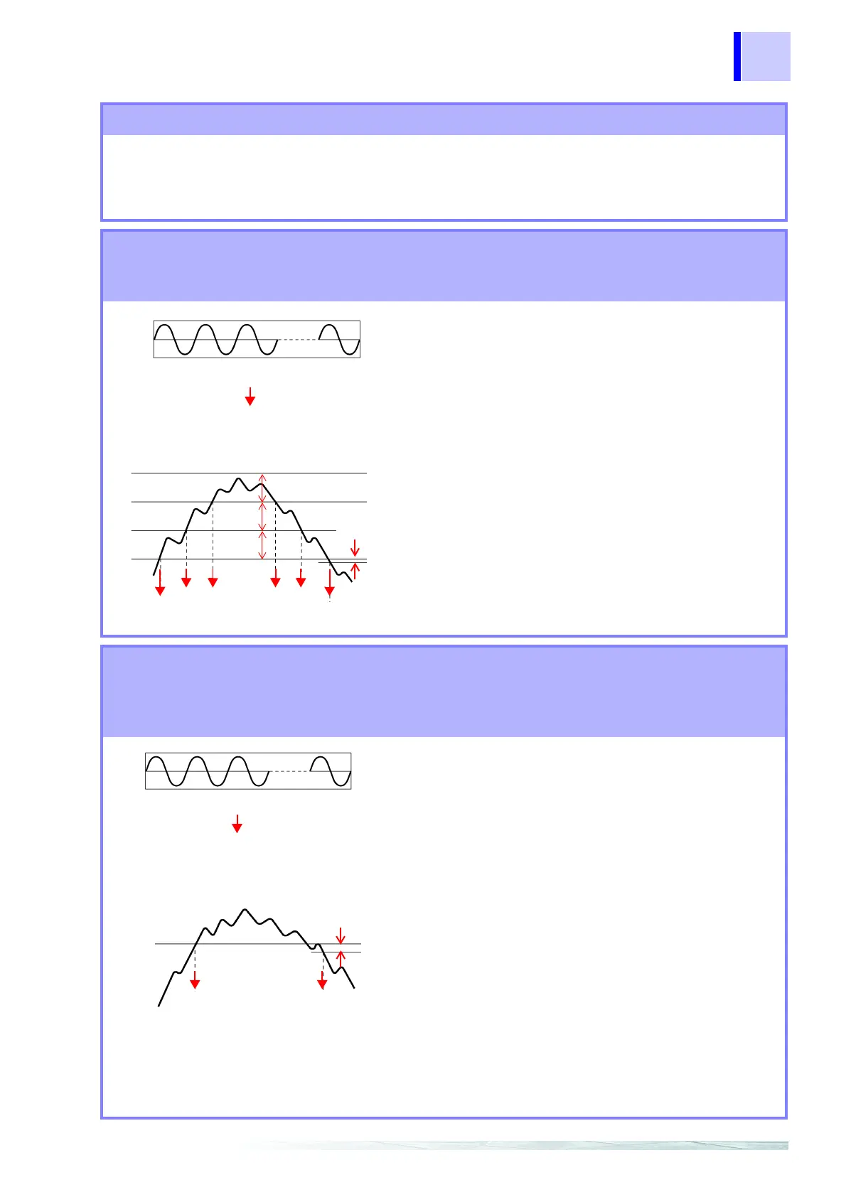
Voltage waveform peaks, current waveform peaks, RMS voltage (upper limit, lower
limit, SENSE), RMS current, active power, reactive power, apparent power, power
factor, and displacement power factor
Detection method:
Measurement and detection at 256 points per cycle
approximately every 200 ms (about once every 10
cycles at 50 Hz, every 12 cycles at 60 Hz, or every
80 cycles at 400 Hz)
With three-phase connection, the voltage calculation
method (either phase-to-neutral voltage or line-to
line voltage) can be specified for
RMS voltage detec-
tion.
Voltage waveform peaks, current waveform peaks,
active power, reactive power, power factor,
and dis-
placement power factor
are detected using thresh-
olds specified as absolute values.
50 Hz: 10 cycles, 60 Hz: 12 cycles,
400 Hz: 80 cycles
RMS calculation
With RMS voltage (upper limit)
SENSE value
Hysteresis
RMS
value
Threshold
SENSE SENSE
EVENT OUT
EVENT
IN
Voltage unbalance factor, current unbalance factor, harmonic voltage, harmonic
current, harmonic power, harmonic voltage-current phase difference, total har-
monic voltage distortion factor, total harmonic current distortion factor, and K fac-
tor
Detection method:
Measurement and detection are performed in a
2048-point rectangular window containing 10 cycles
at 50 Hz, 12 cycles at 60 Hz, or 80 cycles at 400 Hz.
Thresholds can be specified individually for each
harmonic order for
harmonic voltage, harmonic cur-
rent
, harmonic power, and harmonic voltage current
phase difference
.
For
harmonic voltage, harmonic current, and har-
monic power
, detection can be performed using
either of two selectable harmonic calculation meth-
ods (effective value or content percentage).
For
total harmonic voltage distortion factor and total
harmonic current distortion factor
, detection can be
performed using either of two selectable THD calcu-
lation methods (RMS based or fundamental wave
based).
Harmonic power and harmonic voltage current phase
difference
are detected using thresholds specified as
absolute values.
50 Hz: 10 cycles, 60 Hz: 12 cycles,
400 Hz: 80 cycles
Harmonic calculation in a rectangular window
With 3rd order harmonic voltage
Hysteresis
Threshold
EVENT
OUT
EVENT
IN