4.2 Checking the Connection
47
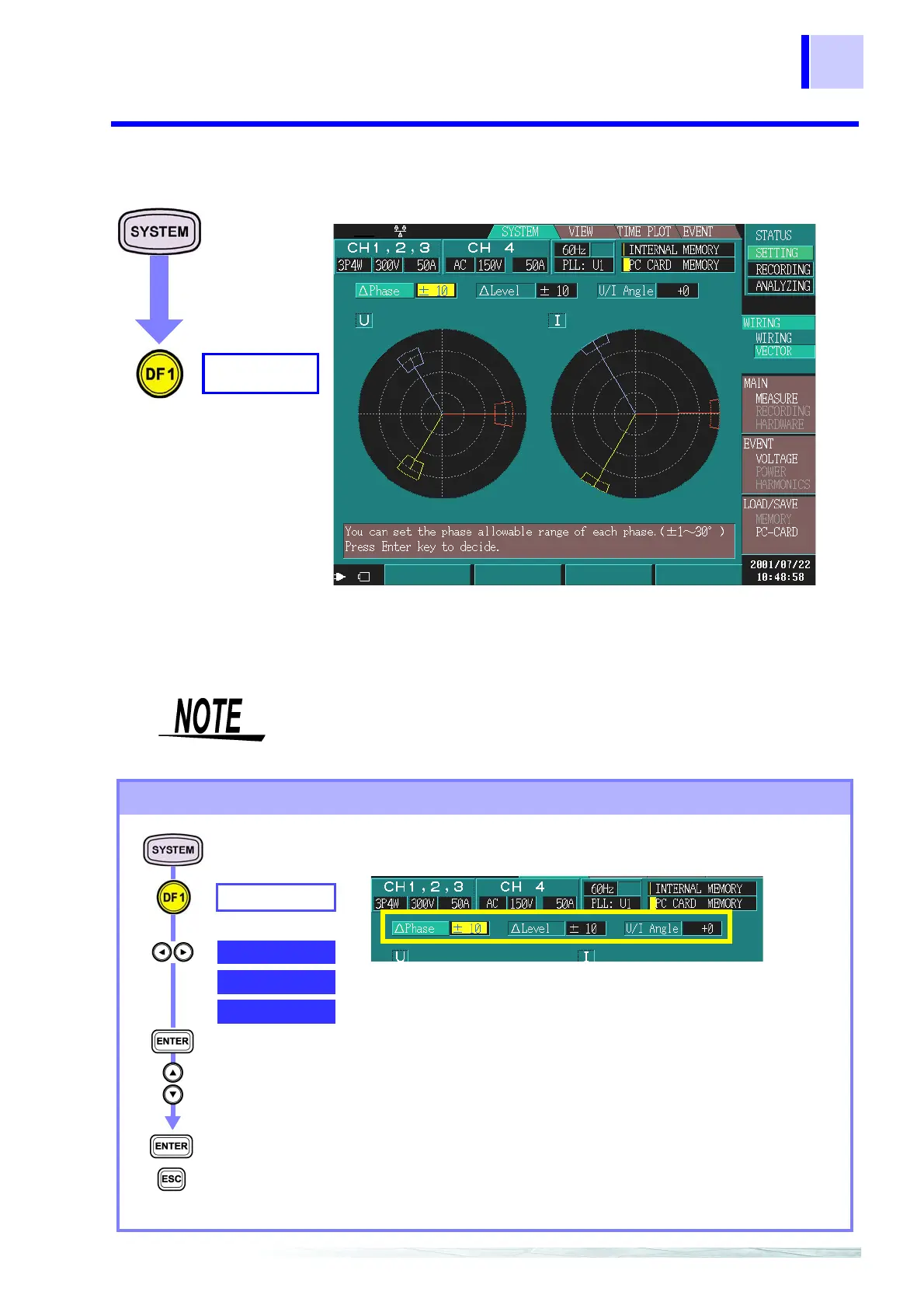
4.2.2 Checking the Connection
You can check the voltage and current vectors of each connection
method.
When tolerance levels are set and the voltage or current falls outside
these levels, check and correct the connection.
WIRING
VECTOR
Example: 3P4W (three-phase four-wire)
When the input level is 50% or less of range, a marker is appended
to the perimeter of the current vector to make it recognizable.
Setting tolerance levels
VECTOR
ΔPhase
Select from pull-
down menu
Confirm
Cancel
ΔPhase
(Phase range)
Tolerance level of each phase in the phase
range
±1 to 30°
ΔLevel
(Oscillation
range)
Tolerance level of each phase in the RMS
value range
±1 to 30%
Set the voltage relative to the nominal voltage
and the current relative to the range.
U/I Angle
(UI phase differ-
ences)
Tolerance level of current phase differences in
relation to voltage
-60° to 60°
ΔLevel
U/I Angle