2.2 Screen Names and Configurations
20
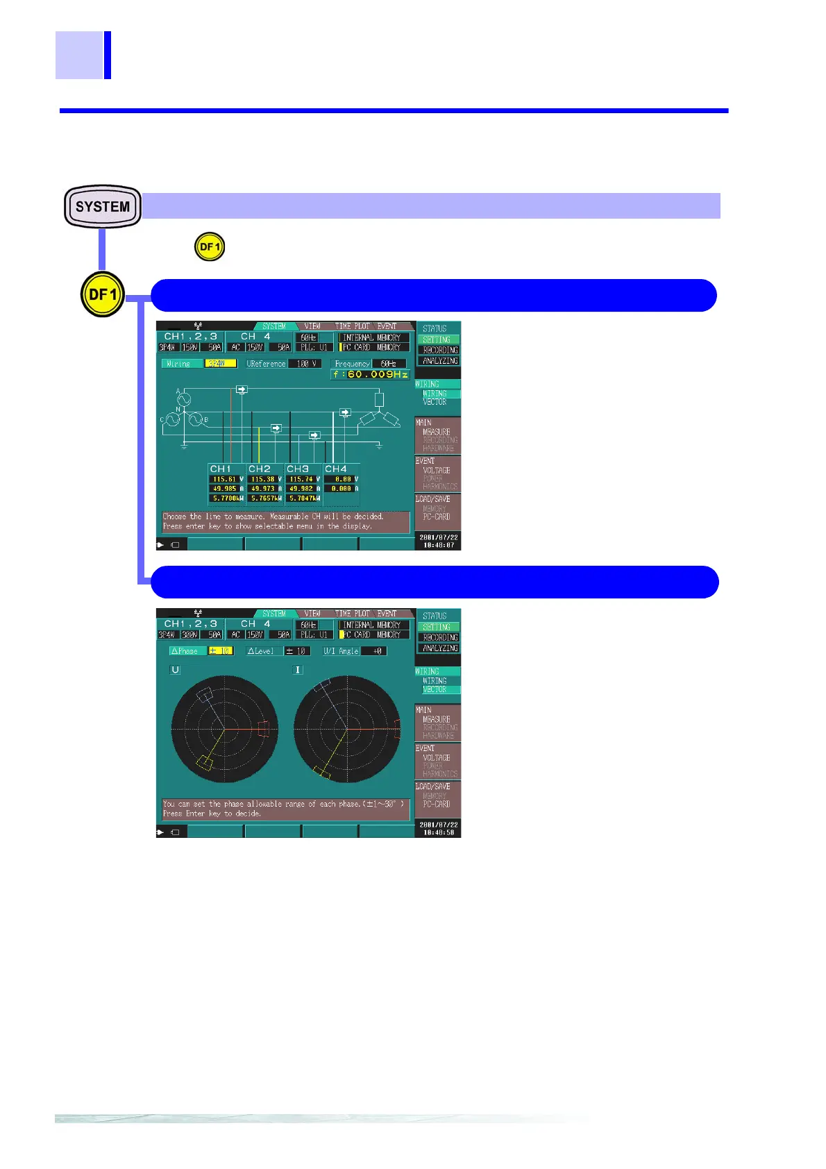
2.2.3 Screen Details
Connection diagram corresponding to
the connection method
Displays (the connection methods for the
voltage cord and clamp and) the voltage
value, current value, and active power
value for each channel.
❖ When the display value is
wrong(page 46)
WIRING 4.2.1 "Confirming the Connection Diagram"(page 45)
VECTOR 4.2.2 "Checking the Connection"(page 47)
Press to switch the display screen.
Displays the vector diagrams of voltage
and current so that you can check the
vectors.
This allows you to determine the RMS
levels and phase differences between
channels.
❖ Setting tolerance levels(page 47)
❖ Tolerance levels are wrong(page
48)
WIRING SYSTEM Screen