6.6 Flicker
111
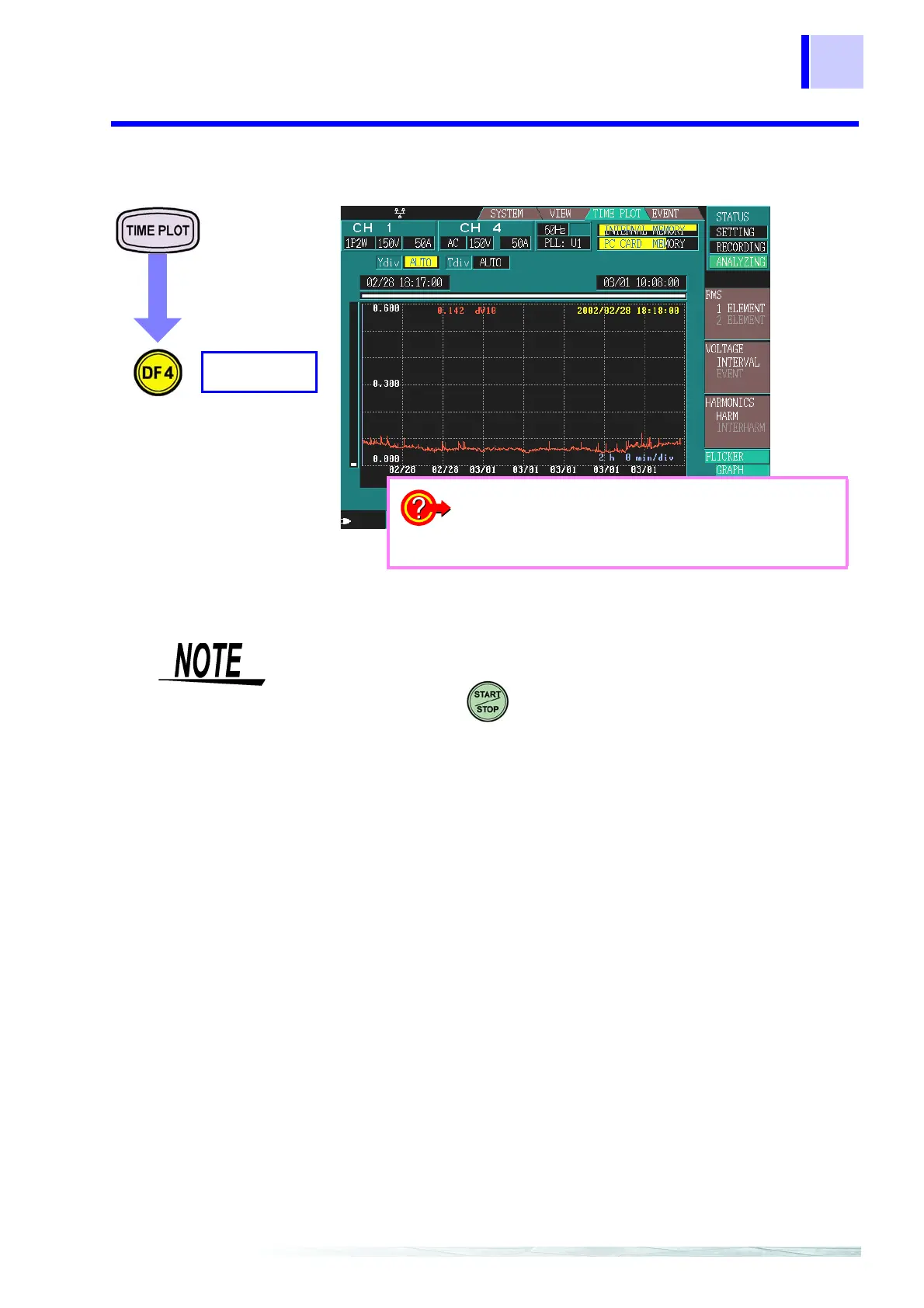
6.6.4 ΔV10 Flicker Graph
Reference volt-
age for Δ V10
flicker
With ΔV10 flicker measurement, the reference voltage is automatically
set internally using AGC (automatic gain control).
Once the fluctuating voltage value has stabilized, the reference volt-
age is automatically changed to that value.
Therefore, unlike conventional ΔV10 flicker meters, there is no need to
switch supply voltage settings.
Example:
Fluctuating voltage: Stabilizes at 96 V rms reference voltage is auto-
matically changed to 96 V rms
Fluctuating voltage: Stabilizes at 102 V rms reference voltage is auto-
matically changed to 102 V rms
Due to the effect of the high pass filter used with Δ V10 flicker, if you
begin measuring Δ V10 immediately after making settings, the Δ V10
flicker measurement value may be unstable, causing the first and sec-
ond settings to display large values.
After making settings on the [SYSTEM] screen, it is recommended
that you wait about 3 minutes before you start measuring.
GRAPH
FLICKER
❖ Changing the Y-axis scale (page 112)
❖ Changing the X-axis scale (page 112)
❖ Cursor measurements (page 112)
❖ Scrolling through waveforms (page 113)
• The graph is updated once a minute, regardless of the interval that is set
for [SYSTEM]-DF2[
MAIN]-[RECORDING].
• After you press , the clock displays “00” seconds and measure-
ment starts.
• This is only displayed if ΔV10 is selected for flicker in [
SYSTEM]-DF2[
MAIN]-[MEASURE].
• ΔV10 flicker can only be measured on one of the voltage channels U1,
U2, or U3.
• The measurement source is the same as the PLL source.