4.2 Checking the Connection
46
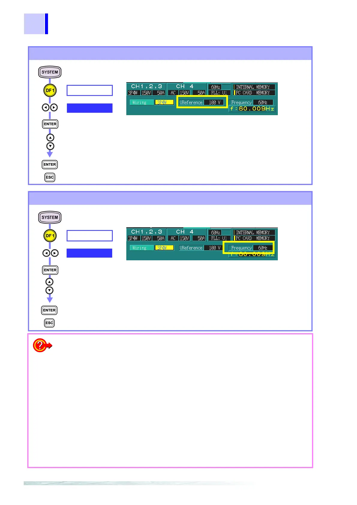
Setting the nominal voltage
WIRING
U Reference
Select from pull-
down menu
Confirm
Cancel
100 V, 101 V, 110 V, 120 V, 200 V, 202 V, 208 V, 220 V, 230 V
240 V, 277 V, 346 V, 380 V, 400 V, 415 V, 480 V, 600 V,
VARIABLE
Nominal voltage affects channels 1 to 3.
(Nominal voltage)
Setting the measured frequency
When the display value
is wrong
1. When the voltage or current display value is lower than
expected
The voltage value is low:
• Is the voltage clip connected to the power line being tested?
• Is the voltage cord inserted in the voltage connector?
The current value is low:
• Is the clamp-on sensor inserted in the device’s current connector?
2. When the active power display value is negative
• Is the voltage cord of the channel displaying the negative value con-
nected properly?
• Is the arrow (printed on the clamp) on the clamp-on sensor for the
channel displaying the negative value pointing to the loaded side?
3. When the voltage display value differs from the expected
value of three-phase connections
• Are the phase-to-neutral voltage and line-to-line voltage (voltage cal-
culation methods) selections different?
❖ "Voltage calculation method settings" (page 54)
WIRING
Frequency
Select from pull-
down menu
Confirm
Cancel
50 Hz, 60 Hz, 400 Hz
Inter-harmonics, flicker and EN50160 cannot be mea-
sured at 400 Hz.
(Measured frequency)