38
❖ 4.2.2 "Checking the Connection"(page 47)
❖ 4.2.1 "Confirming the Connection
Diagram"(page 45)
❖ 4.2 "Checking the Connection"(page 45)
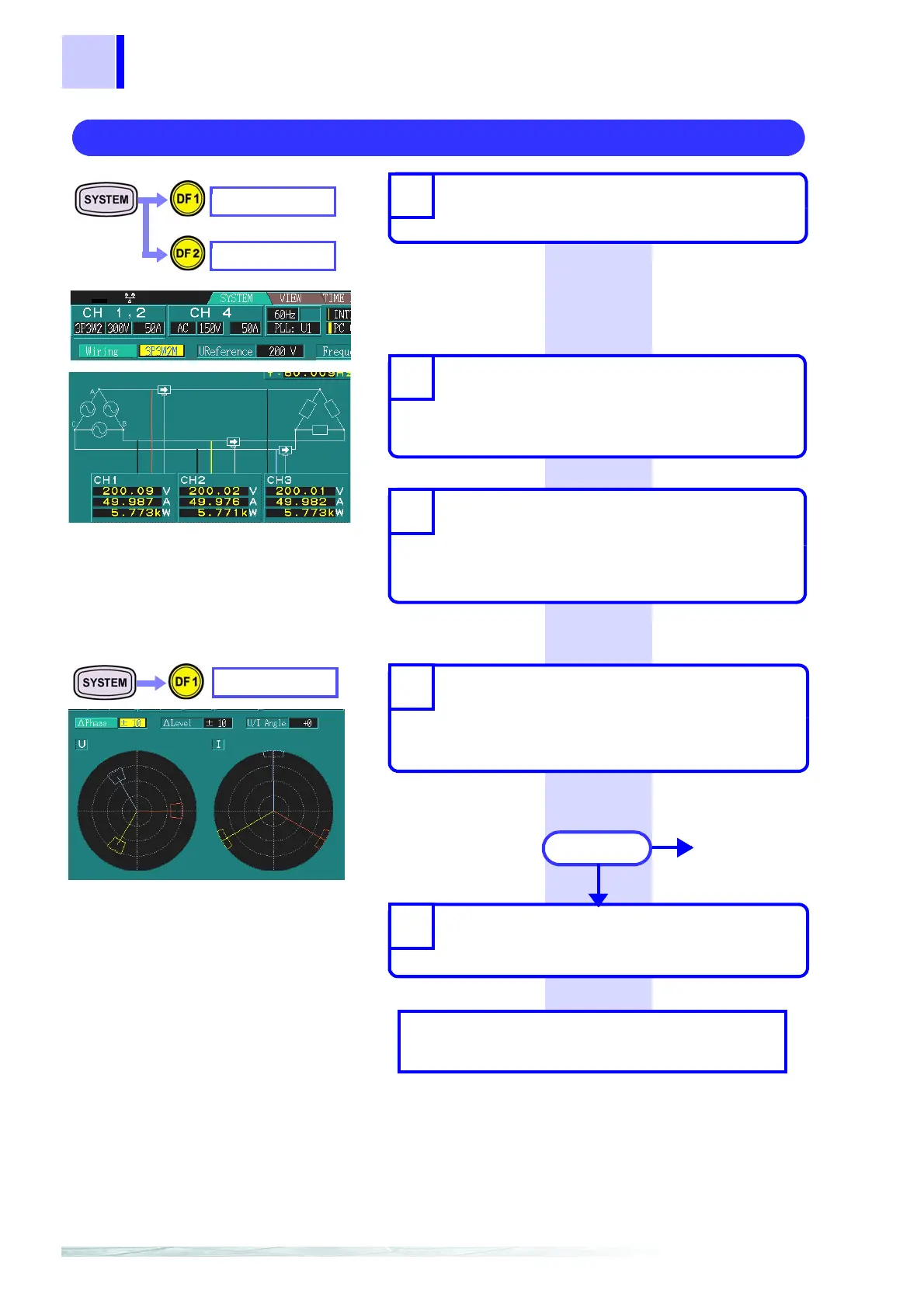
OK
NG
Go to 2
Measurement/analysis
WIRING
VECTOR
2. Connecting to the target power line.
MEASURE
dvanced
ettings
❖ Chapter 4 "Making System Settings
(SYSTEM Screen)"(page 43)
❖ Chapter 5 "Using Waveforms, Vec-
tors, DMMs, and Bar Graphs (VIEW
Screen)"(page 65)
❖ Chapter 6 "Using the Time Series
Graph (TIME PLOT Screen)"(page
79)
❖ Chapter 7 "Using Events (EVENT
Screen)"(page 115)
Set the connection method, nominal
voltage, and frequency.
1
While consulting the connection
diagram, connect the voltage cord
and clamp sensor to the power line
that you want to measure.
2
Confirm the present connection sta-
tus.
(voltage, current, and active power on each
channel)
3
Check the connection status and
set the tolerance levels.
(Check the oscillation and phase for the volt-
age and current in the vector.)
4
Depending on your application,
make recording and event settings.
5
Result