10.2 Timing Chart
197
10
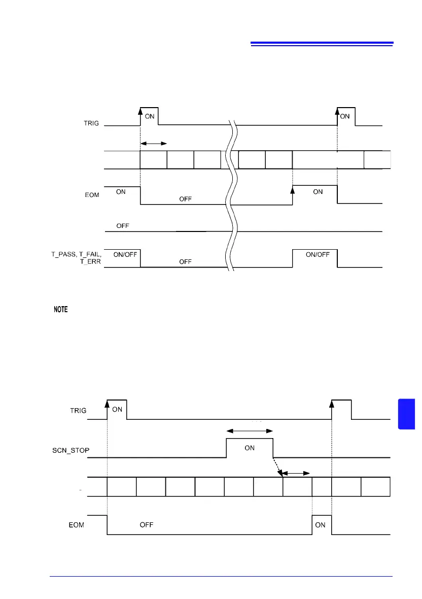
(2) Scan function: Auto
Measurement is performed while switching all channels after one trigger input.
• The channel judgment result (HI, IN, LO, ERR) signals and BCD signal are not output.
Only the judgment result (T_PASS, T_FAIL, T_ERR) signals are output.
• The INDEX signal does not turn on for each channel. It turns on after the completion of
scanning.
• During scanning, the TRIG, CAL, and 0ADJ signals are ignored without being held.
SCN_STOP operation
State
Judgment result/
BCD
Switching time
Switching
processing
Channel 1
Measure-
ment
Switching
processing
Switching
processing
Channel 20
Measure-
ment
Switching
processing
Channel 1
Measure-
ment
Judgment result/ BCD: HI, IN, LO, ERR, PASS, FAIL, BCDm-n, RNG_OUT0 to 3
In this example, channels 1 through 20 have been set to ON.
State
10 ms or more
Approx. 15 ms
Switching
processing
Channel 1
Measure-
ment
Switching
processing
Channel 2
Measure-
ment
Switching
processing
Channel 3
Measure-
ment
Rest
processing
Switching
processing
Channel 1
Measure-
ment