Servo Drive Configuration E1 Series Servo Drive Thunder Software Operation Manual
4-30 HIWIN MIKROSYSTEM CORP.
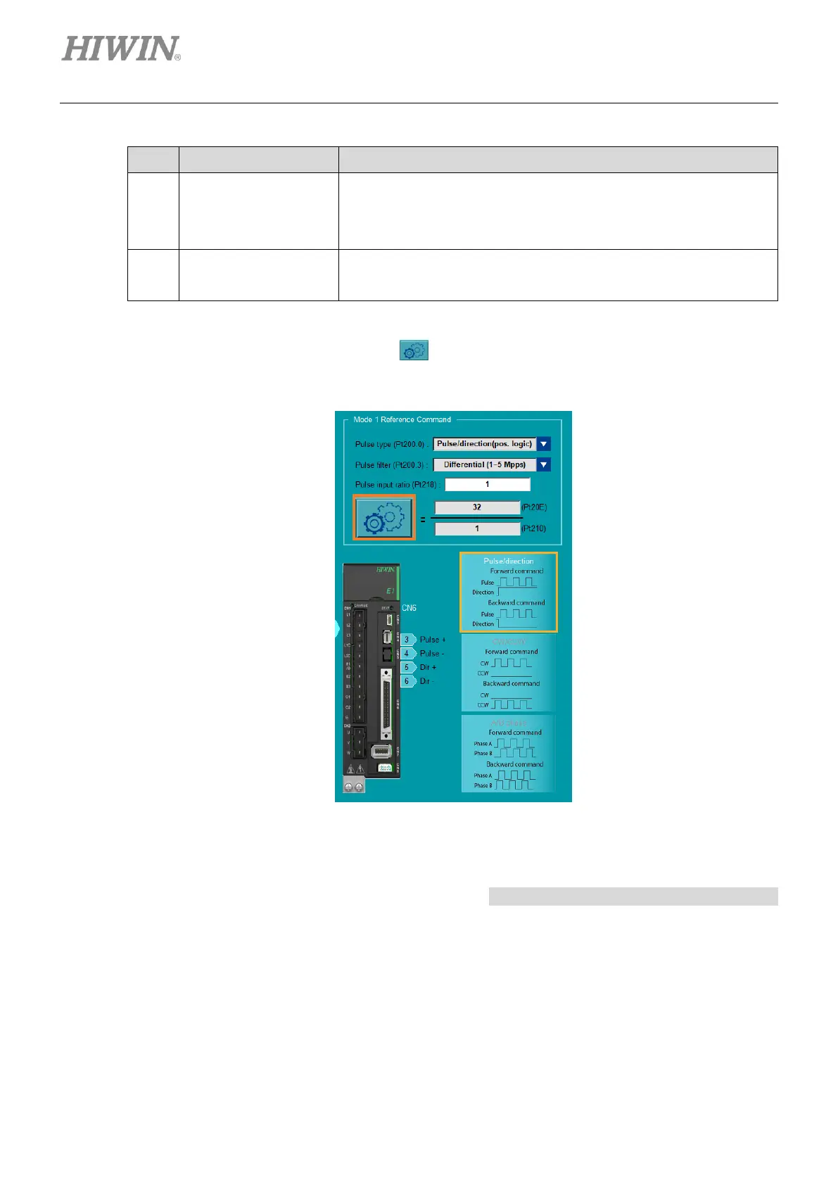
Pulse format
parameters setting
Select pulse type (Pt200.0) and pulse filter (Pt200.3), and set pulse
input ratio (Pt218). Refer to section 8.4 in “E1 Series Servo Drive
User Manual” for further descriptions of pulse command input.
It shows the CN6 pin diagram of pulse command input signal and the
pulse signal diagram.
3. Click electronic gear ratio setting icon to open “Electronic gear ratio setting” window for
electronic gear ratio setting.
Figure 4.3.6.2.6
“Electronic gear ratio setting” window only supports standard servo drive, and it will display
different window based on encoder setting. Refer to Linear motor’s electronic gear ratio setting
for the related information.
 Loading...


