Servo Drive Configuration E1 Series Servo Drive Thunder Software Operation Manual
4-26 HIWIN MIKROSYSTEM CORP.
Velocity command
input gain (Pt300)
Set the ratio of analog voltage and motor rated velocity. Refer to section
8.3.1 in “E1 Series Servo Drive User Manual” for the example of velocity
command input.
It shows the CN6 pin diagram of velocity command input signal and the
input range diagram of velocity command voltage.
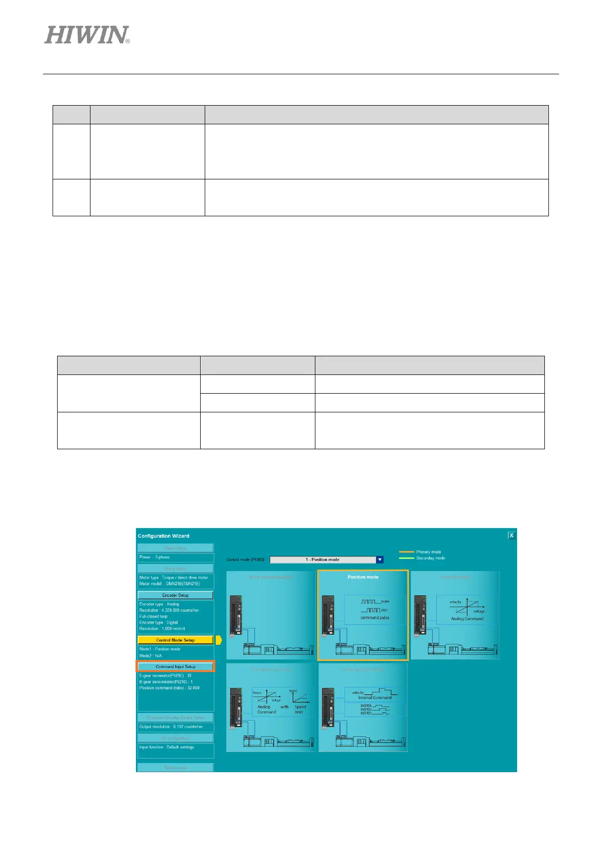
4.3.6.2 Position mode
Position mode’s command input setup shows different setting window based on servo drive model, motor
setup and encoder setup.
Table 4.3.6.2.1
Rotary motor’s pulse command input setup
Linear motor’s pulse command input setup
Fieldbus servo drive’s position command input
setup
◼ Rotary motor’s pulse command input setup
1. Click Command Input Setup to enter command input setup page.
Figure 4.3.6.2.1

 Loading...


