Page 84 SLG 700 SmartLine Level Transmitter User’s Manual Revision 8
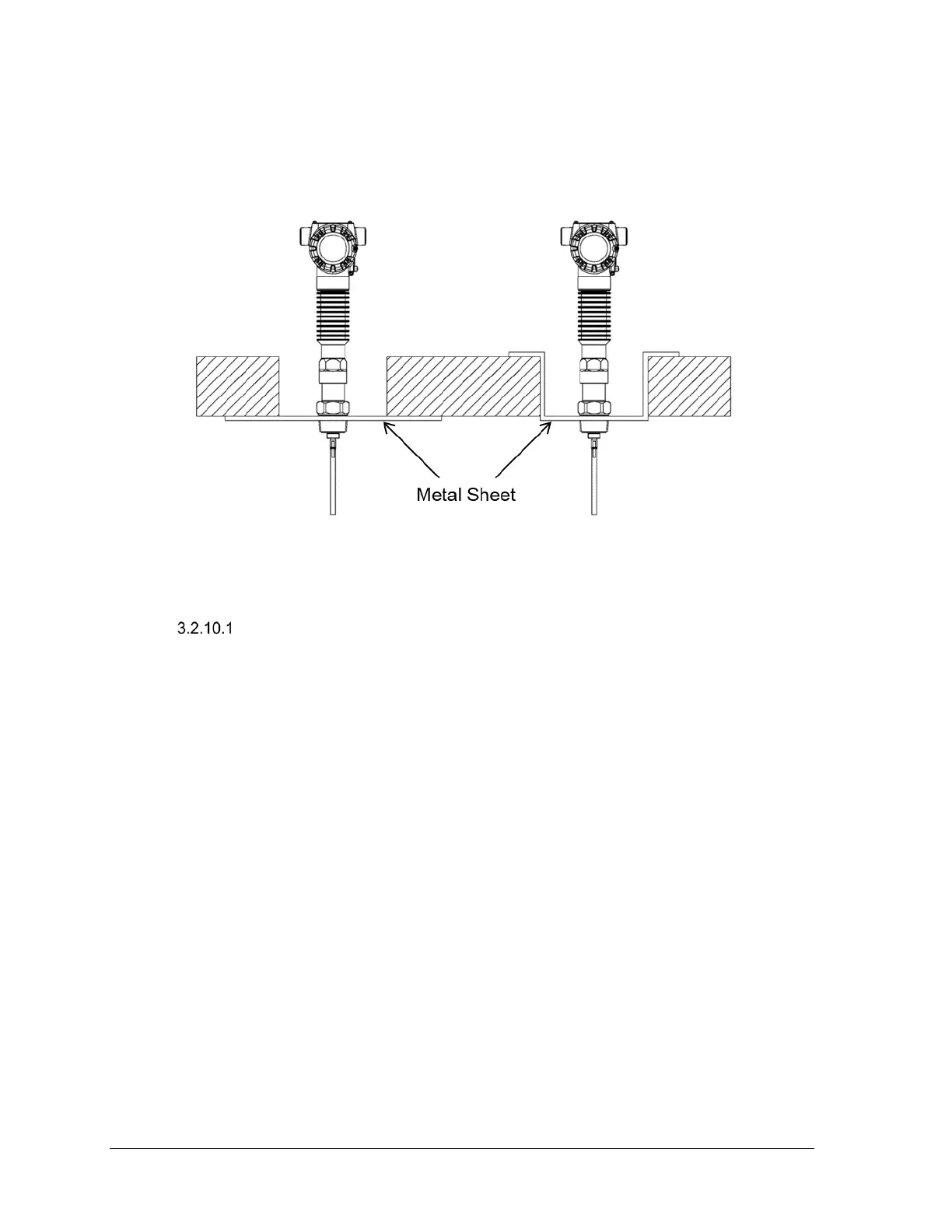
Figure 3-38 depicts an example of mounting in concrete silos, the placement of the concrete
versus the metal sheet used to secure the transmitter. Both Figure 3-37 and Figure 3-38 are
considered non-metallic mounts. Both types of mountings are subject to the same
specifications.
Figure 3-38: Mounting in concrete silos
Remote mount
In applications where a remotely mounted display is required, the remote mount allows
the electronics housing to be mounted 3-m away from the process connector. This can be
useful when access to the mounting location is limited. To assemble the remote mount,
mount the process connector to the tank first, then secure the mounting bracket to a pipe
or wall. Secure the electronics module to the bracket with the 3 supplied M6 screws.
Connect the cable and check bends for minimum radius (see Figure 3-39) to prevent
damage. Torque the 2 nuts to 6Nm (4.4ft-lbs). Note that if separating the cable from the
process connector or the electronics, care must be taken to avoid damaging the o-rings.
O-ring lubricant may help to avoid damage.
 Loading...


