Revision 8 SLG 700 SmartLine Level Transmitter User’s Manual Page 139
20. Apply O-ring lubricant to the end cap o-ring before installing the end cap. Reinstall the
end cap and tighten the end cap locking screw.
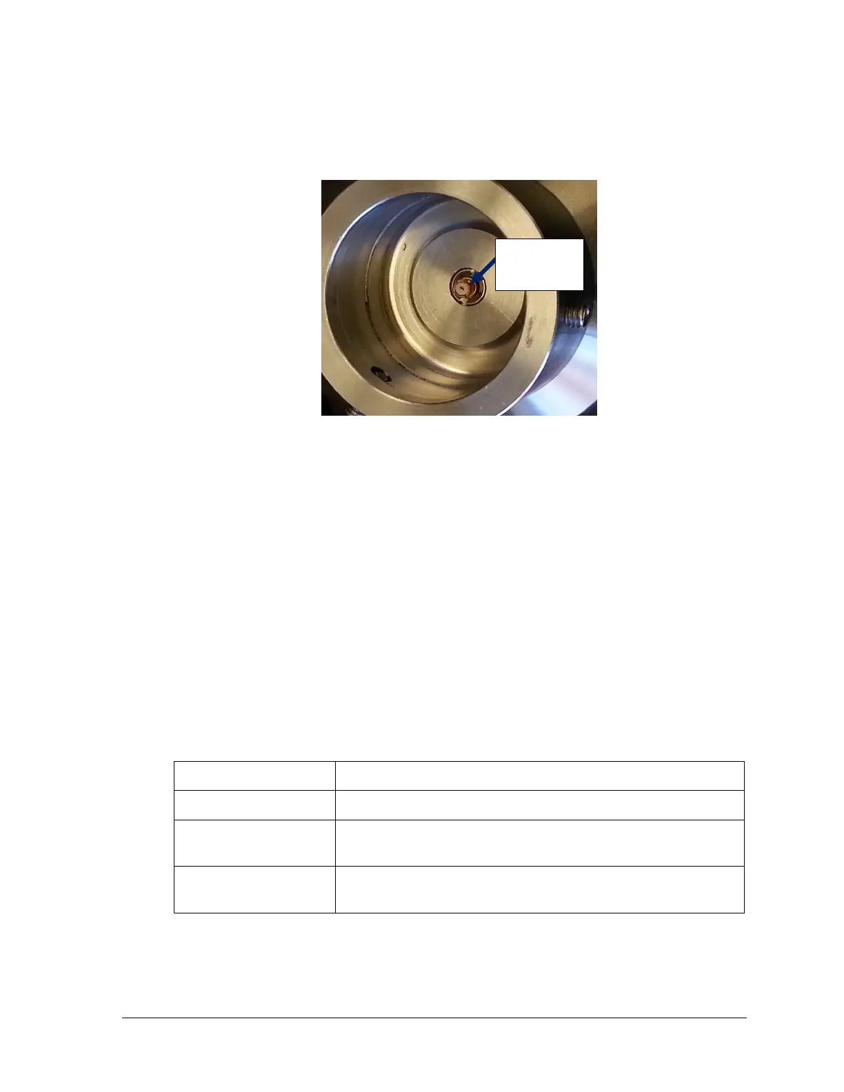
21. Ensure the small RF connector is seated firmly in place, on the bottom of the sensor
electronics housing. See Figure 5-10.
Figure 5-10: Location of RF-connector at bottom of sensor housing
22. If necessary, replace the o-ring at the top of the process connector. Apply o-ring
Lubricant and carefully replace the Sensor electronics housing without pinching the
o-ring. Tighten the set screws.
23. Turn ON transmitter power.
If the COMM Firmware version is 1.020000 the transmitter should power up
and operate with no further configuration required. However, if a warning
message is displayed, it may be necessary to identify if a new sensor electronics
housing is being installed, or a new COMM module is being installed.
If the COMM Firmware version is 1.010000, the model key information will not
be visible unless the information was programmed at factory. This does not
affect the operation of the transmitter.
24. If upgrading transmitter from sensor firmware version 1.000x00, the transmitter
configuration will need to be set. However, if a new COMM module was ordered at
the same time as the sensor electronics a basic configuration will be already in place.
See manuals:

 Loading...


