Page 124 SLG 700 SmartLine Level Transmitter User’s Manual Revision 8
5. Set each jumper to the desired position (UP/OFF or DOWN/ON).
See Table 4-10 and Table 4-11.
6. If applicable, re-install the Display module as follows:
• Orient the display as required.
• Install the Interface Connector in the Display module such that it will mate
with the socket for the display in the Communication module.
• Carefully line up the display, and snap it into place. Verify that the two tabs
on the sides of the display latch.
Installing a Display Module into a powered transmitter may cause a
temporary upset to the loop output value.
Orient the Display for proper viewing through the end cap window. You can rotate
the mounting orientation in 90
°
increments.
Restore transmitter power if removed.
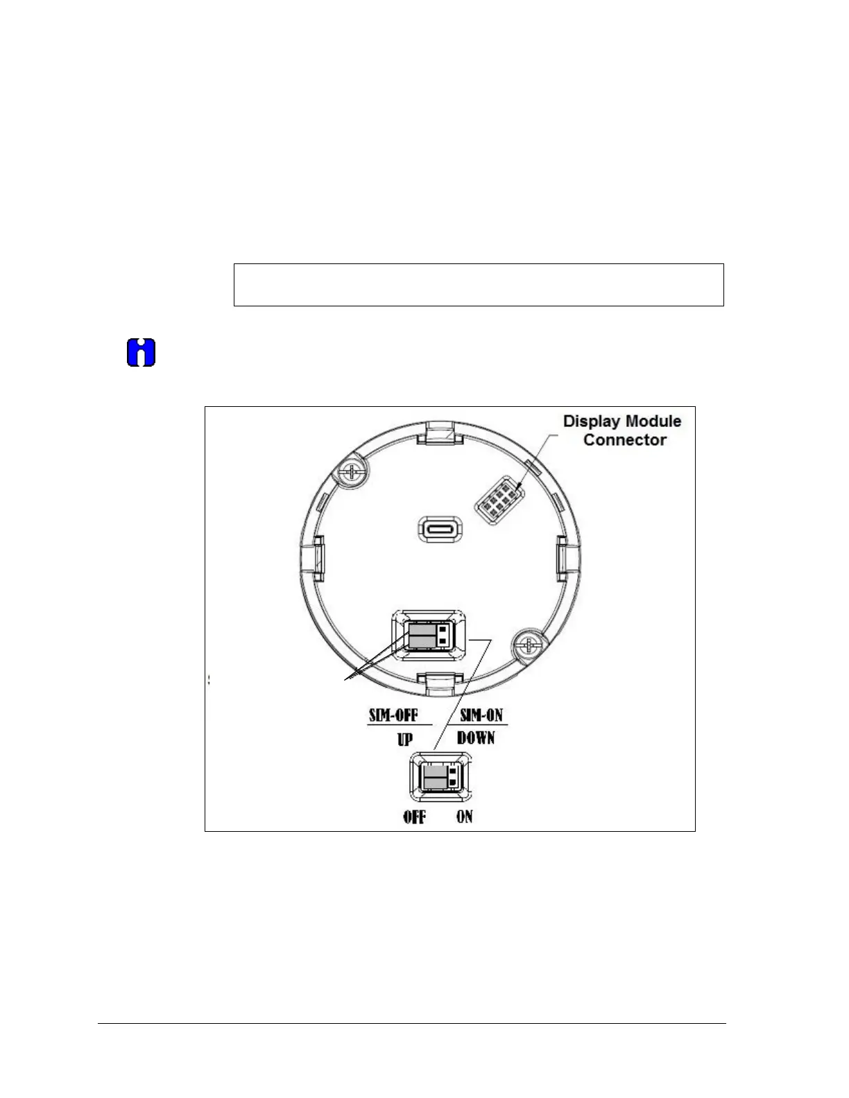
Figure 4-3: Locating the Failsafe and Write Protect Jumpers

 Loading...


