EasyManuals Logo

Honeywell SmartLine SLG 700 User Manual

Honeywell SmartLine SLG 700
198 pages
To Next Page IconTo Next Page
To Previous Page IconTo Previous Page
Page #98 background imageLoading...
Page #98 background image
Page 82 SLG 700 SmartLine Level Transmitter User’s Manual Revision 8
Mounting on a bypass / bridle
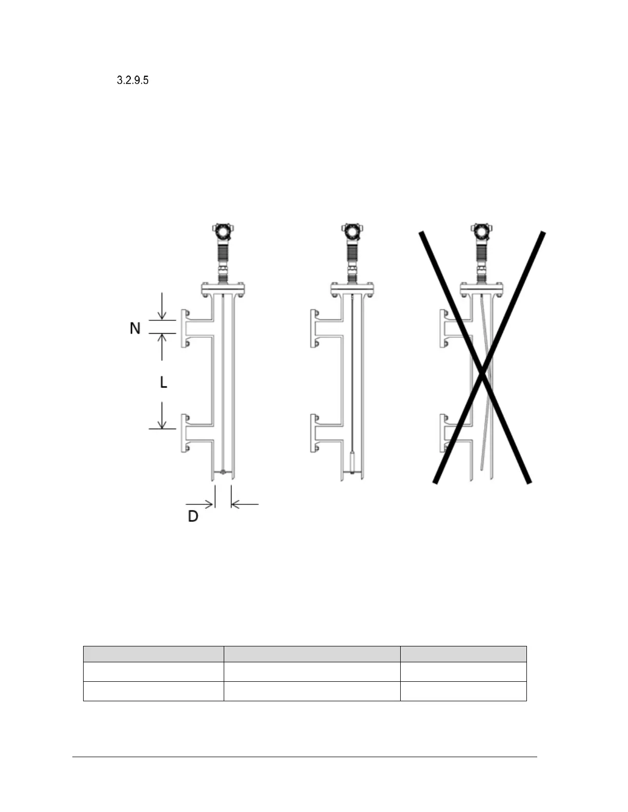
SLG 700 transmitter can be successfully installed in a new or existing bypass pipe,
bridle, or a side pipe as shown Figure 3-36: Bypass installation. This type of installation
is often simpler and allows the addition of radar level measurement to an otherwise busy
installation.
A similar installation is also possible inside the main container, when installing the SLG
700 transmitter on a stilling well.
N = Inlet diameter
L = Effective measurement range (≥ 12“/300mm)
D = Bypass diameter (N<D)
Figure 3-36: Bypass installation
Table 3-18: SLG720 bypass and stillwell recommended diameters
Probe type
Recommended diameter
Minimum diameter
Rod probe
3 or 4 (75mm or 100mm)
2 (50mm)
Wire probe
4 (100mm)
2 (50mm)

Table of Contents

Questions and Answers:

Question and Answer IconNeed help?

Do you have a question about the Honeywell SmartLine SLG 700 and is the answer not in the manual?

Honeywell SmartLine SLG 700 Specifications

General IconGeneral
BrandHoneywell
ModelSmartLine SLG 700
CategoryTransmitter
LanguageEnglish

Related product manuals