Revision 8 SLG 700 SmartLine Level Transmitter User’s Manual Page 135
assembly
2. Remove power from transmitter.
3. If a new terminal assembly is also being installed follow instructions 34-ST-33-64.
The relevant part numbers are listed in Table 7-1.
GWR Level Terminator Module w/Lightning Protection Kit
for HART Modules
GWR Level Terminator Module w/Lightning Protection Kit
for FF Modules
GWR Level Terminator Module w/o Lightning Protection Kit
for HART Modules,
GWR Level Terminator Module w/o Lightning Protection Kit
for FF Modules
4. If a new Communications Module is also being installed follow instructions 34-ST-33-69.
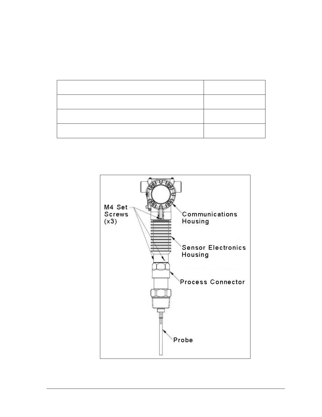
5. Separate the sensor housing from the process connector by first loosening the 4 mm setscrews
(3) and gently separating the sensor electronics housing. Do not discard setscrews or o-rings.
Figure 5-6: Location of sensor housing and attachment set screws

 Loading...


