Page 152 SLG 700 SmartLine Level Transmitter User’s Manual Revision 8
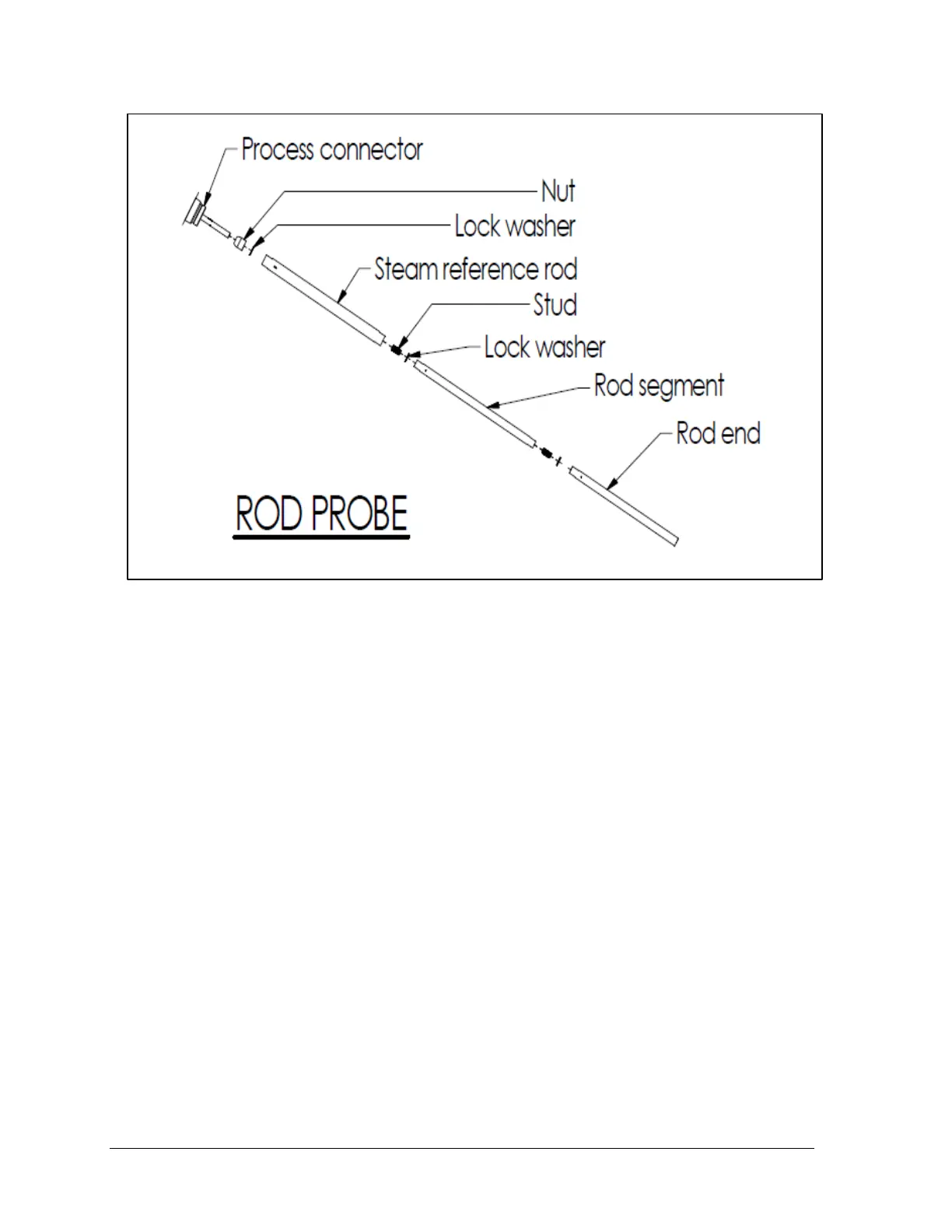
Figure 5-17 - Saturated steam application rod probe assembly
Step – 9: Reassemble the rest of the rod probe using the lock washer and M10x30 stud included in
the retrofit kit.
Step – 10: For coaxial probe, slip the coaxial outer tube over the rod and tighten to the process
connector. Torque the connection to 30 Nm (22 ft-lbs). It is recommended that a process
compatible thread locking compound (i.e. Loctite 242) be used on the outer conductor threaded
joints. Install end spacer between central conductor and outer tube in the counterbore. Secure end
spacer using the retaining ring. Refer to Figure 5-18.

 Loading...


