Revision 8 SLG 700 SmartLine Level Transmitter User’s Manual Page 7
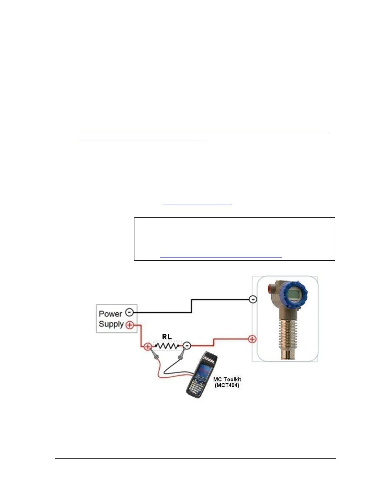
Figure 2-2 is an example of a HART connection to the transmitter. The communication
resistor RL may be inserted anywhere in the 4-20 mA loop but it is recommended to be
installed close to the positive supply. Refer to section 0 for acceptable power supply and RL
ranges
The MC Toolkit is a dedicated Honeywell communication tool that uses Device Description
(DD) files to communicate with multiple transmitter models. Also, other equivalent tools or a
HART-to-USB converter may be used. Device Description files are available from:
HONEYWELL: Go to:
https://www.honeywellprocess.com/en-US/explore/products/instrumentation/process-level-
sensors/Pages/smartline-level-transmitter.aspx
Select the “Software” tab.
Scroll/search for file name:
“HART Device Description (DD) files for Honeywell HART Devices”
This .zip file contains the latest version of the DD files for all of Honeywell’s HART field
devices.
Unzip the file to locate the DD files applicable to the SLG 700 series.
HART
®
FOUNDATION: http://en.hartcomm.org
Device Descriptions (DD) are HART data files which are
gathered from field device manufacturers which describes the
features and functions of a device.
HART provides a detailed definition here:
http://en.hartcomm.org/hcp/tech/faq/faq.html

 Loading...


