Page 38 SLG 700 SmartLine Level Transmitter User’s Manual Revision 8
3.2 Mechanical Installation
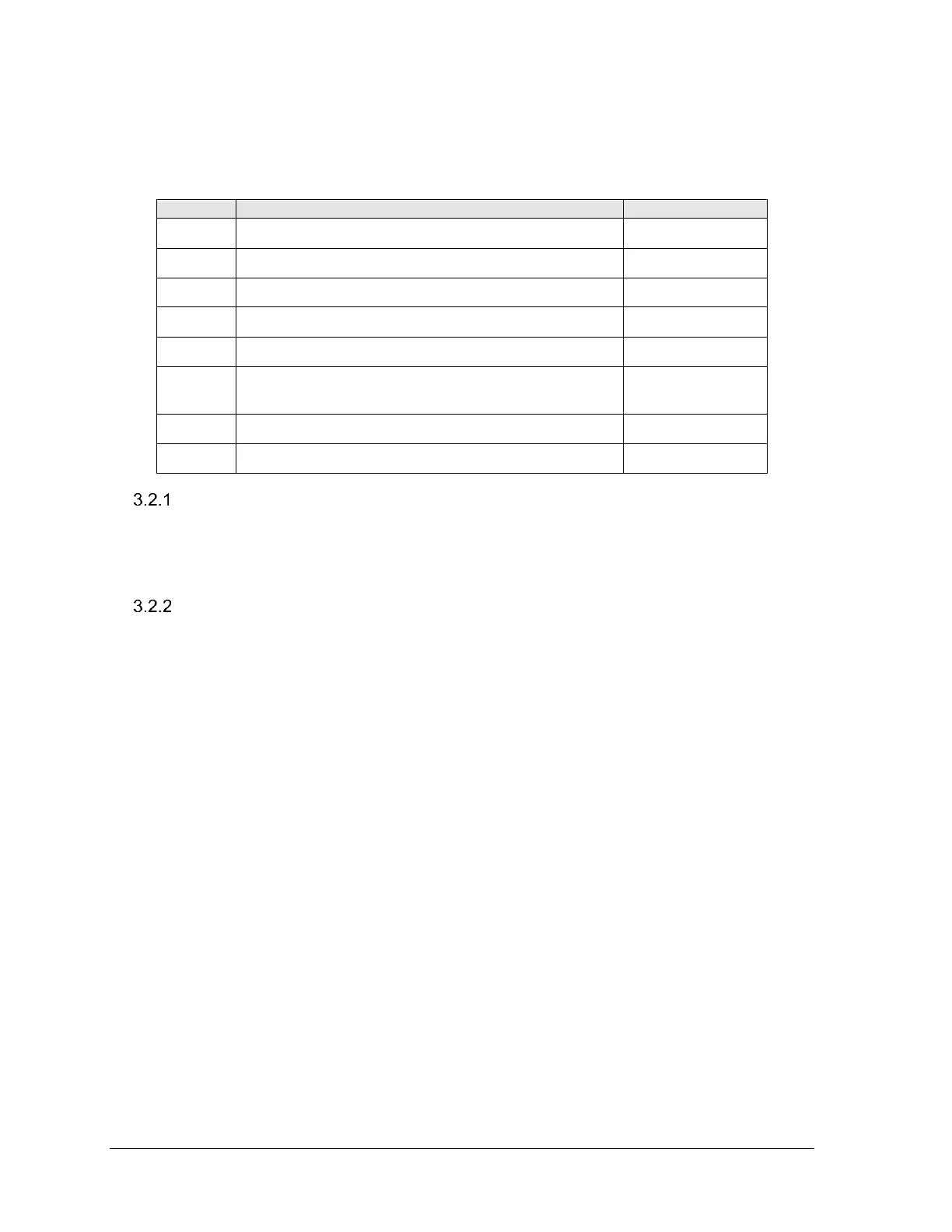
Follow the steps in Table 3-2. See Section 3.3.1 for wiring and configuration steps.
Table 3-2: Mechanical installation sequence
Check probe dimensions and strength.
Trim probe to correct length.
Attach/assemble the probe to the process connector.
Attach centering disk to probe if applicable.
Rotate electronic housing to desired view angle (on
models with optional display).
Install conduit entry plugs and adapters.
Check for correct probe dimensions and strength
Measure for correct probe length and check that your probe is within tensile or bending
load limits. See section 3.2.2.1 for details.
See Table 3-14: Probe length for different probe types
Accuracy and measuring range specifications
See section 2.4.3

 Loading...


