EasyManuals Logo
Home>Honeywell>Transmitter>SmartLine SLG 700

Honeywell SmartLine SLG 700 User Manual

Honeywell SmartLine SLG 700
198 pages
To Next Page IconTo Next Page
To Previous Page IconTo Previous Page
Page #153 background imageLoading...
Page #153 background image
Revision 8 SLG 700 SmartLine Level Transmitter User’s Manual Page 137
:
Figure 5-8: Rook Assembly
WARNING: Do not tightly screw together the Sensor Housing into the
Electronics Housing. The connection should be to the point where the o-
ring is not visible.
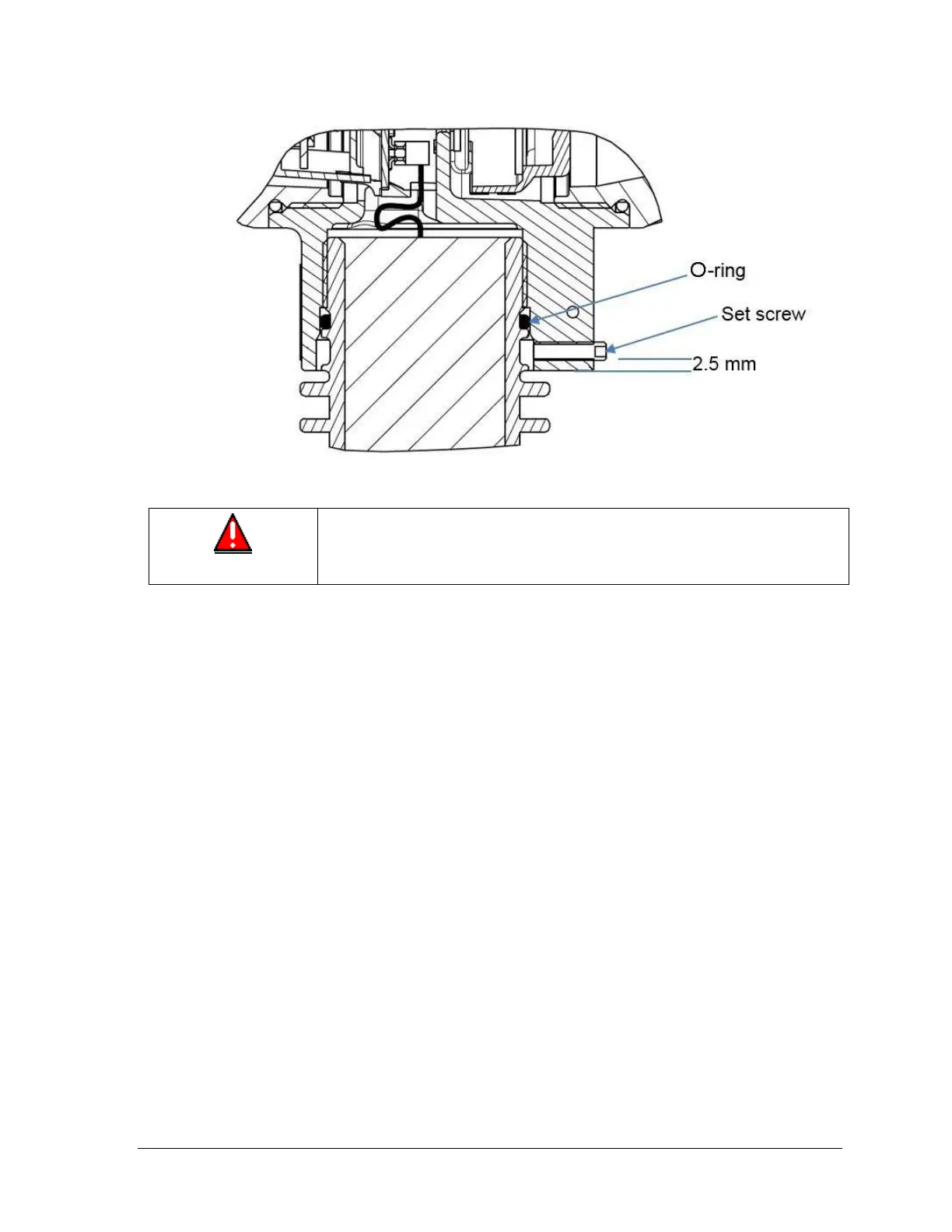
14. Tighten set screw as shown in Figure 5-8. The set-screw should not protrude from the
Communications electronics housing. Protrusion indicates that the sensor housing is
screwed an incorrect amount into the communications housing.
15. Carefully align and connect the Sensor Ribbon Cable to the connector “P2” at the bottom
of the Communication Module. Pin 1 must be aligned with contact 1 of the ribbon cable
indicated by the colored edge wire.

Table of Contents

Questions and Answers:

Question and Answer IconNeed help?

Do you have a question about the Honeywell SmartLine SLG 700 and is the answer not in the manual?

Honeywell SmartLine SLG 700 Specifications

General IconGeneral
BrandHoneywell
ModelSmartLine SLG 700
CategoryTransmitter
LanguageEnglish

Related product manuals