Page 138 SLG 700 SmartLine Level Transmitter User’s Manual Revision 8
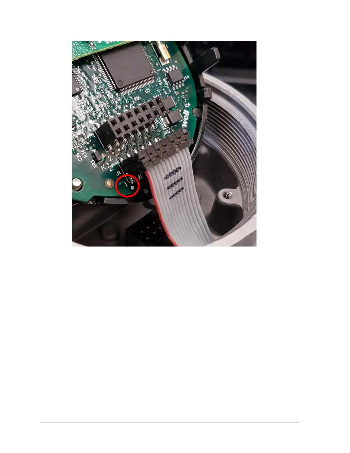
Figure 5-9: - Sensor ribbon cable
Note: Sensor ribbon cable wire aligns with pin 1 of J4 as shown. The Communication
Module is then rotated 180 degrees to seat in Communications Housing.
16. Carefully, insert the Communication Module into the Electronics housing compartment.
Ensure that the Sensor Ribbon Cable is not pinched.
17. Tighten the two Communications Module retaining screws.
18. If a new Communications Module is being used, duplicate the jumper settings on the
original Module.
19. If applicable, re-install the Display Module as follows:
Orient the display as desired.
Install the Interface Connector in the Display Module such that it will mate with the
socket for the display in the Communication Module.
Carefully line up the display, and snap it into place. Verify that the two tabs on the
sides of the display latch.

 Loading...


