Page 134 SLG 700 SmartLine Level Transmitter User’s Manual Revision 8
Tools required.
WARNING: When installed as explosion-proof or flame-proof in a
hazardous location, keep covers tight while the transmitter is energized.
Disconnect power to the transmitter in the non-hazardous area prior to
removing end caps for service. When installed as non-incendive or
non-sparking equipment, disconnect power to the transmitter in the
non-hazardous area, or determine that the location is non-hazardous
before disconnecting or connecting the transmitter wires.
M4 set screw for Separating Sensor Electronics
Housing from Process Connector and
Communications Housing
M3 set screw for end cap removal
Parker Super O-ring Lubricant
or equivalent
1. Determine transmitter Firmware version of the Sensor and Communications Modules
COMM PCBA and ADVANCED DISPLAY
must be replaced or have firmware
upgraded.
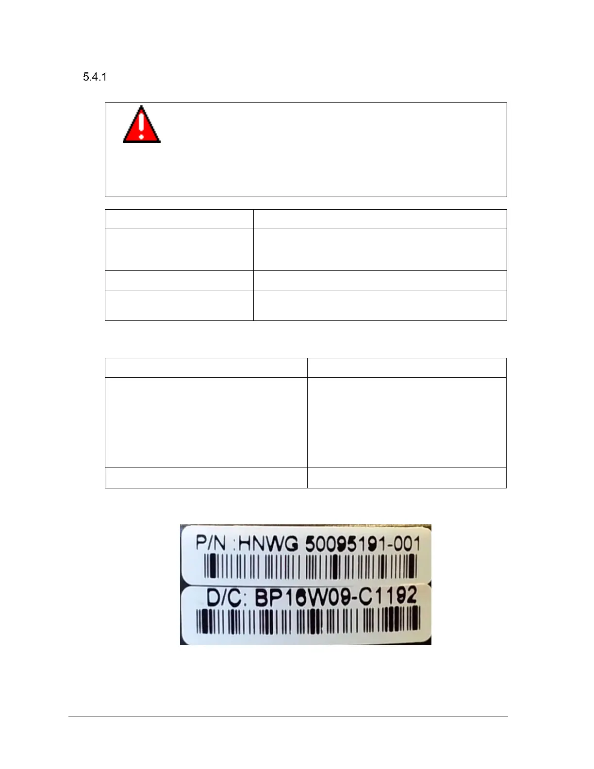
TERM PCBA must be replaced if the
version number in the date code is not ‘C’.
An example of a correct date code is shown
in Figure 5-45-5
1.010000, 1.020000, and 2.000100
Sensor electronics is replaceable
Figure 5-45-5: Part Number and Date Code (D/C) label on bottom of Terminal PCBA

 Loading...


