Page 18 SLG 700 SmartLine Level Transmitter User’s Manual Revision 8
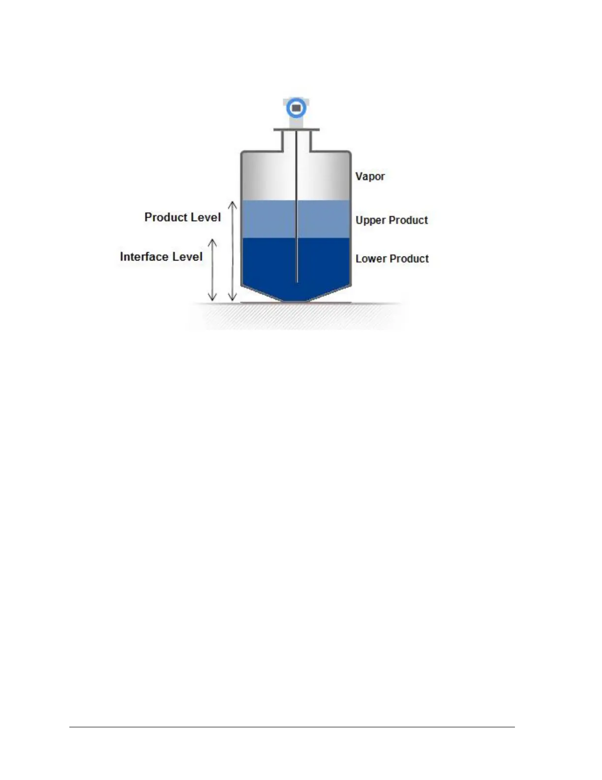
Figure 2-3: Interface measurement
2.3 Signal processing configuration
SLG 700 series level transmitters employ advanced signal processing techniques in order to
get the most accurate measurements possible.
Complete pulse-shape information including amplitude, width and side-lobe attenuation is
used for level detection in order to minimize the influence of signal interferences. A typical
pulse and the associated parameters is shown on Figure 2-4.
The sensor is programmed with default values for all parameters, determined by the dielectric
constants of the materials being measured. Either through the advanced display or using the
Honeywell DTM (SLG 700 HART option manual 34-SL-25-06) these parameters can be
adjusted to match the measurement conditions. Typically, the amplitude (also referred to as
gain) of the model is the only parameter that needs to be adjusted, and this is generally only
required if the dielectric constant of the medium is uncertain. Note that the ‘attenuation’
parameter of the model should not be confused with the attenuation of the radar pulse as it
propagates down the waveguide.

 Loading...


