Page 48 SLG 700 SmartLine Level Transmitter User’s Manual Revision 8
Technical Assistance Center (TAC): 800-822-7673 in North America or 1-602-313-5558
from the rest of the world.
Coaxial probe consists of inner rod and coaxial outer tube. To trim the
coaxial probe, both inner rod and coaxial outer tube need to be trimmed.
For trimming the inner rod, refer to rod probe trimming instruction detailed
above. Avoid trimming the internal thread region of the inner rod.
To trim the coaxial outer tube, start on the terminating segment (the one
with the unthreaded end). Mark and trim the outer tube to the same
amount as the inner rod. Avoid trimming the coupler region of the outer
tube.
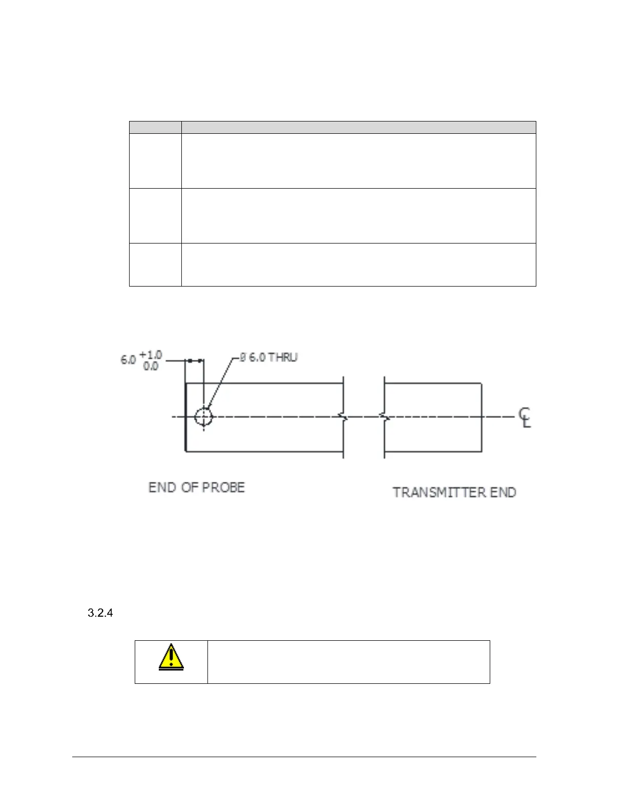
Drill a 6mm hole through the end of the outer tube at location shown in
Figure 3-8: Drill 6-mm diameter hole at the position shown on the coaxial
outer conductor..
Figure 3-8: Drill 6-mm diameter hole at the position shown on the coaxial outer
conductor.
Attach/assemble the probe
CAUTION: To reduce the risk of damage from electrostatic
discharge, ensure the Electronic Housing is grounded
before lowering a probe into a tank.

 Loading...


