Revision 8 SLG 700 SmartLine Level Transmitter User’s Manual Page 93
Loop current wiring should never be connected to the TEST “+” terminal. This
can damage the Transmitter.
Additionally, never connect the current measurement device between the
Loop “+” terminal and the TEST “+”terminal. This also will damage the
Transmitter.
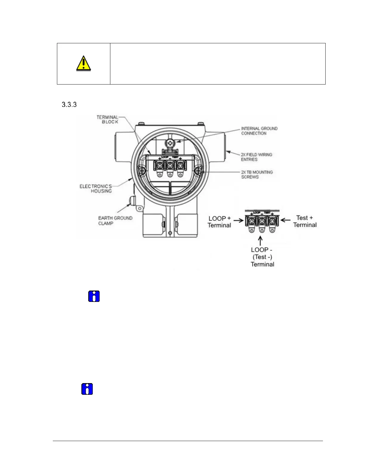
Terminal Connections
Figure 3-45: HART 3-Screw Terminal Board and Grounding Screw
A FOUNDATION Fieldbus terminal block has a 2-screw terminal
board, The Test+ terminal is not present.
As shown in Figure 3-45, each Transmitter has an internal and external terminal to
connect it to earth ground. Grounding the transmitter is recommended for safety, to
minimize the possible effects of noise, and affords protection against lightning and static
discharge. A lightning-protection terminal block can be configured or ordered and
installed in place of a non-lightning terminal block for Transmitters that will be installed
in areas that are susceptible to lightning strikes.
Note: The lightning-protection terminal block is red, the regular terminal blocks are black.
Wiring must comply with local codes, regulations and ordinances.
Grounding may be required to meet various approval body certification,for
example CE conformity. Refer to the Appendix of this document for details.

 Loading...


