Home
Honeywell
Transmitter
SmartLine SLG 700
Honeywell SmartLine SLG 700 User Manual
5
of 1
of 1 rating
198 pages
Give review
Manual
Specs
To Next Page
To Next Page
To Previous Page
To Previous Page
Loading...
Revision 8
SLG 700 SmartLine Level Transmitt
er User’s Manual
Page
67
Figure 3-
20
: Probe length defini
tion for rod probes using a
centering disk
Mount
ing
the transmitter
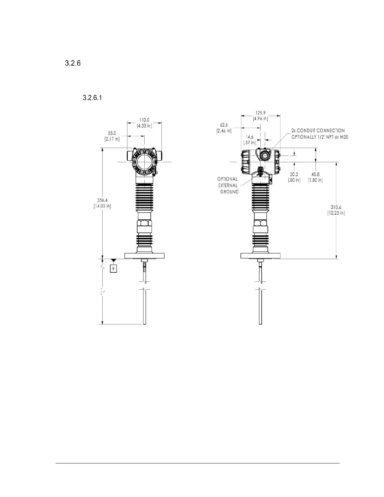
In the following dimension figures, “R” denotes th
e transmitter reference plane.
SLG720 Transmi
tter dimensions
Figure 3-
21
: Flanged SL
G720 Transmitter, mm [
in
]
82
84
Table of Contents
Default Chapter
7
Table of Contents
7
1 Introduction
17
Overview
17
Transmitter Models
17
Transmitter Components
17
Overview of Components
17
Table 2-1: Features and Options
17
Electronics Housing
18
Figure 2-1: Components of the Level Transmitter
18
Sensor Housing
19
Process Connector
19
Table 2-2: Available Smartline GWR Display Characteristics
19
Probe
20
Table 2-3: Probe Selection
20
Communicating with the Transmitter
22
Ma HART
22
Foundation
22
TM Fieldbus (FF)
22
Figure 2-2: Example of HART Connection RL
23
Figure 2-3: Example of FF Connection
24
DTM-Based Tools and Experion
25
SLG 700 Transmitter Nameplate
27
Figure 2-4: Example of a FF Network
27
Figure 2-5: Transmitter Nameplate Example
28
Transmitter Model Number Description
29
Safety Certification Information
29
Safety Integrity Level (SIL)
29
Figure 2-6: Standard SLG 700 Model Number
29
Figure 2-7: Safety Certification Example
29
Security Considerations
30
Measurement Options Licensing
30
2 Radar Level Measurement
31
Overview
31
Theory of Operation
31
Figure 2-1: GWR Measurement
32
Figure 2-2: Sample Echo Curve
33
TDR for Interface and Flooded Measurements
33
Signal Processing Configuration
34
Figure 2-3: Interface Measurement
34
Amplitude Tracking
35
Figure 2-4 Radar Impulse Reflection Model
35
Full-Tank Detection
35
Maximum Fill Rates, Latching and Timeouts
36
Signal Interferences and Background Echoes
37
Field and Obstacle Background
37
Static and Dynamic Backgrounds
37
Accuracy and Measurement Range Specifications
38
Figure 2-5: Upper Transition Zone Length and Minimum Blocking Distance High (BDH) and Minimum Blocking Distance Low (BDL) for Coax Probes in Water
39
Figure 2-6: Upper Transition Zone Length and Minimum Blocking Distance High (BDH) and Minimum Blocking Distance Low (BDL) for Coax Probes in Oil
39
Figure 2-7: Transition Zone Lengths and Minimum Blocking Distance High (BDH) for Single Lead Probes in Water
40
Figure 2-8: Transition Zone Lengths and Minimum Blocking Distance High (BDH) for Single Lead (I.e. Rod and Rope) Probes in Oil
41
Figure 2-9 Minimum Blocking Distances, Steam Application for a Threaded HTHP Process Connector
41
Figure 2-10 Minimum Blocking Distance, Steam Application for a Flanged HTHP Process Connector
42
Table 2-1: Blocking Distance High
42
Process Applications
44
Single Liquid
44
Two Liquid Applications
44
Figure 2-11: Two-Liquids Flooded
44
Figure 2-12: Two-Liquids Non-Flooded
45
Low Dielectric Applications
46
Steam Boiler Applications
47
Figure 2-13 Typical Echo Steam Application Echo with Vapor Reference Rod
47
Process Condition Considerations
48
Turbulence
48
Foam or Emulsions
48
FEP Probe
48
Container Considerations
49
Shapes
49
Materials (Plastic Vs. Metal)
49
Figure 2-14: Top Vertical and Angled Mounting
49
Blocking Distance High and Blocking Distance Low Guidance
50
Blocking Distance High (BDH) Guidance
50
Blocking Distance Low (BDL) Guidance
50
Blocking Distance, Full Tank Detection and Latching Modes
50
3 Transmitter Installation
52
Preparation
52
Installation Sequence
52
Table 3-1: Installation Sequence
52
Tools
53
Mechanical Installation
54
Check for Correct Probe Dimensions and Strength
54
Accuracy and Measuring Range Specifications
54
Table 3-2: Mechanical Installation Sequence
54
Table 3-3: Sensor Details - All Models
55
Table 3-4: Minimum Blocking Distances and Transition Zones for the Various Probe Types
55
Table 3-5: Minimum Blocking Distances and Minimum Distance to Inlet or Surface with DC Corrected Level for the Saturated Steam Application
55
Table 3-6: Maximum Measurement Range for each Probe Type Versus Dielectric Constant
55
Figure 3-1 SLG720 Probe Dimensions, MM [In]
56
Figure 3-2: SLG720 FEP Probe Dimensions, MM [In]
57
Figure 3-3: SLG726 Threaded Process Connection Probe Dimensions; MM [In]
58
Figure 3-4 SLG726 Flanged Process Connection Probe Dimensions; MM [In]
59
Figure 3-5: SLG726 Saturated Steam Application Threaded Process Connection Probe Dimensions; MM [In]
60
Figure 3-6: SLG726 Saturated Steam Application Flanged Process Connection Probe Dimensions; MM [In]
60
Table 3-7: Tensile Load Limits for Flexible Probe
61
Table 3-8: Rigid (I.e. Rod and Coaxial) Probe Mounting Angle Limits
61
Table 3-9: Rod Probe Bending Torque Limits (All Lengths)
61
Table 3-10: Coaxial Probe Bending Load Limits (All Lengths)
61
Trim the Probe Length
63
Figure 3-7: Example Bending Torque Values
63
Attach/Assemble the Probe
64
Figure 3-8: Drill 6-MM Diameter Hole at the Position Shown on the Coaxial Outer Conductor
64
Figure 3-9: Rod Probe Assembly
65
Figure 3-10: SLG726 Flanged Process Connection, Probe Nut Installation Position, MM [In]
66
Figure 3-11: Wire Probe Assembly
67
Figure 3-13: SLG720 Coaxial Probe Assembly (Single Outer Tube Depicted)
68
Figure 3-12: SLG720 Coaxial Probe Assembly (Single Outer Tube Depicted)
70
Figure 3-14: SLG726 Coaxial Probe Assembly
75
Figure 3-15 Saturated Steam Application Rod Probe Assembly
76
Figure 3-16: Saturated Steam Application Coaxial Probe Assembly
76
Centering Disks and Configured Probe Length
77
Table 3-11: Recommended Probe Diameter and Material of Construction
77
Figure 3-17: Recommended Location of Holes for Rod Probes
79
Figure 3-18: Centering Disks for Wire and Rod Probes
80
Figure 3-19: Centering Disks for FEP Coated Wire and Rod Probes
80
Table 3-12: Centering Disk Determination from Pipe Size and Schedule
81
Table 3-13: Centering Disk Dimensions
81
Table 3-14: Probe Length for Different Probe Types
82
Mounting the Transmitter
83
Figure 3-20: Probe Length Definition for Rod Probes Using a Centering Disk
83
Figure 3-21: Flanged SLG720 Transmitter, MM [In]
83
Figure 3-22: Threaded (NPT ¾", 1", 1½", 2") SLG720 Transmitter, MM [In]
84
Figure 3-23: Threaded (BSP/G ¾", 1", 1½") SLG720 Transmitter, MM [In]
85
Figure 3-24: Flanged SLG726 Transmitter, MM [In]
86
Figure 3-25: Threaded (NPT 1½", 2") SLG726 Transmitter, MM [In]
87
Figure 3-26: Threaded (BSP/G 1½") SLG726 Transmitter, MM [In]
88
Suitable Mounting Position
89
Figure 3-27: Mounting Position
89
Table 3-15: Minimum Recommended Distance to Container Wall and Obstacles (MM)
89
Optimum Operating Temperature
90
Temperature Requirements
91
Figure 3-28: SLG720 Temperature Limits
91
Figure 3-29: SLG726 Temperature Limits
92
Figure 3-30: SLG726 Maximum Pressure Based on Maximum Operating Temperature
92
Table 3-16: SLG726 Maximum Pressure Based on Maximum Operating Temperature in Tabular Form
93
Figure 3-31: Flanged Tank Connection
94
Figure 3-32: Flange Mounting
95
Table 3-17: SLG720: Recommended Nozzle Dimensions
95
Figure 3-33: Oversized Nozzle Configuration
96
Figure 3-34: Threaded Tank Connection
97
Figure 3-35: Tank Roof Mounting Using Threaded Connection
97
Figure 3-36: Bypass Installation
98
Table 3-18: SLG720 Bypass and Stillwell Recommended Diameters
98
Mounting on a Non-Metallic Container
99
Figure 3-37: Mounting on a Non-Metallic Vessel
99
Table 3-19: SLG726 Bypass and Stillwell Recommended Diameters
99
Figure 3-38: Mounting in Concrete Silos
100
Figure 3-39: Remote Mount
101
Rotate Transmitter Housing
102
Secure the Probe
102
Figure 3-40: Rotate Transmitter Housing
102
Figure 3-41: Anchoring Wire Probes
103
Figure 3-42: Wire Probe Slack
103
Figure 3-43: Anchoring Coaxial Probes
104
Install Conduit Entry Plugs and Adapters
105
Table 3-20: Conduit Entry Plug Installation
105
Table 3-21: Conduit Adapter Installation
105
Flange Pressure Ratings
106
Material Exposed to Tank Atmosphere
106
Electrical Installation
107
Wiring a Transmitter
107
HART / 4-20Ma Voltage Operating Ranges
107
Figure 3-44: Transmitter Operating Ranges
107
Terminal Connections
109
Figure 3-45: HART 3-Screw Terminal Board and Grounding Screw
109
FOUNDATION Fieldbus
110
Wiring Procedure
110
Lightning Protection
111
Supply Voltage Limiting Requirements
111
Process Sealing
111
Explosion-Proof Conduit Seal
111
4 Operating the Transmitter
112
User Interface Options
112
Transmitter Advanced Displays with Buttons
112
DTM or DD - HART and FF
112
Three-Button Operation
113
Three-Button Operation Without Display
113
Figure 4-1: Three-Button Option
114
Menu Navigation
115
Data Entry
115
Table 4-1: Three-Button Option Functions
115
Editing a Numeric Value
116
Selecting a New Setting from a List of Choices
116
Table 4-2: Three-Button Data Entry
116
The Advanced Display Menu
117
Table 4-3: Advanced Display Main Menu Structure
117
Correlation Model Recalculation
118
Table 4-4: Correlation Model Recalculation
118
Table 4-5: Display Config Sub-Menu
119
Table 4-6: Basic Configuration Sub-Menu
121
Table 4-7: Advanced Config Sub-Menu
125
Table 4-8: Monitor Sub-Menu
130
Monitoring the Advanced Display
136
Advanced Displays
136
Figure 4-2: Advanced Display Formats with the Process Variable
136
Table 4-9: Advanced Displays with PV Format Display Indications
137
Button Operation During Monitoring
138
Changing the Failsafe Direction and Write Protect Jumpers (Including Simulation Mode)
139
Procedure to Establish Failsafe Operation
139
Figure 4-3: Locating the Failsafe and Write Protect Jumpers
140
Table 4-10: HART Failsafe and Write Protect Jumpers
141
Table 4-11: FOUNDATION Fieldbus Simulation and Write Protect Jumpers
141
5 Maintenance
142
Overview
142
Preventive Maintenance Practices and Schedules
142
Procedures
145
Output Check Procedures
145
Constant Current Source Mode Procedure
146
Figure 5-1: Current Loop Test Connections
146
Replacing the Terminal Block
147
Replacing the Display Assembly
147
Replacing the Communication Module
147
Figure 5-2: Electronic Housing Components
147
How to Replace the Sensor Housing
148
Figure 5-3: Sensor Housing
148
Figure 5-45-5: Part Number and Date Code (D/C) Label on Bottom of Terminal PCBA Assembly
150
Tools Required
150
Figure 5-6: Location of Sensor Housing and Attachment Set Screws
151
Figure 5-7: Communications Housing Assembly
152
Figure 5-8: Rook Assembly
153
Figure 5-9: - Sensor Ribbon Cable
154
Figure 5-10: Location of RF-Connector at Bottom of Sensor Housing
155
Hazardous Locations
156
Appendix: Reconciling Model Numbers
156
Figure 5-11- Model Number Mismatch Critical Error
157
Figure 5-12 - Reconcile Model Numbers Feature
157
Replacing the Wire Probe
158
Tools Required
158
Procedures
159
Table 5-1: Probe Length Calculated from Spare Probe Model Number
161
Trimming Coaxial Probes
163
Tools Required
163
Procedure
163
Figure 5-13 - no Trimming Zones on Outer Tube and Inner Rod
164
Figure 5-14 - Drill Hole Position on Outer Tube
165
Figure 5-15 - Spacer and Locking Pin Installation
165
Saturated Steam Probe Installation
166
Tools Required
166
Procedure
166
Figure 5-16 - SLG726 Flanged Process Connection, Probe Nut Installation Position, MM [In]
167
Figure 5-17 - Saturated Steam Application Rod Probe Assembly
168
Figure 5-18 - Saturated Steam Application Coaxial Probe Assembly
169
6 Troubleshooting
170
Error Messages
170
Diagnostics
170
Table 6-1: SLG 700 Standard Diagnostics Messages
171
Diagnosing SLG720 Coaxial Probe Misassembly
173
7 Parts List
177
Overview
177
Table 7-1: Parts
177
8 Glossary
178
9 Appendix Certifications
181
Safety Instrumented Systems (SIS) Installations
181
European Directive Information (EU)
181
Hazardous Locations Certifications
182
Marking ATEX Directive
187
Conditions of Use for Ex Equipment, "Hazardous Location Equipment" or "Schedule of Limitations
188
Control Drawing
190
China Rohs
194
10 Security
195
How to Report a Security Vulnerability
195
5
Based on 1 rating
Ask a question
Give review
Questions and Answers:
Need help?
Do you have a question about the Honeywell SmartLine SLG 700 and is the answer not in the manual?
Ask a question
Honeywell SmartLine SLG 700 Specifications
General
Brand
Honeywell
Model
SmartLine SLG 700
Category
Transmitter
Language
English
Related product manuals
SmartLine SLN 700 Series
54 pages
Honeywell SmartLine ST 700
274 pages
Honeywell SmartLine ST700
9 pages
Honeywell STT750 SmartLine
72 pages
Honeywell SmartLine ST 800
144 pages
Honeywell SmartLine STIW400
106 pages
Honeywell SMV800
220 pages
Honeywell SMV 3000
217 pages
Honeywell ST 800
122 pages
Honeywell STT25H
40 pages
Honeywell STT850 Series
118 pages
5894PI - Ademco Wireless PIR Motion Sensor
4 pages