For single lead probes, avoid nozzles > 8" (200 mm) in diameter nozzles, particularly when
measuring low dielectric constant materials. The user will need to install a smaller inner
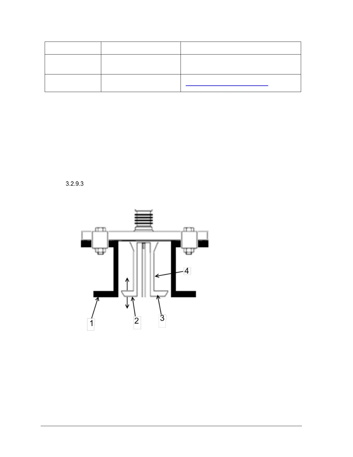
nozzle when operation with these larger nozzle diameter required, see Figure 3-33: Oversized
nozzle configurationfor inner nozzle design requirements.
For supported nozzles, the minimum upper blocking distance and transition zone distance
must be increased by the height of the nozzle. Additionally, in order to achieve the minimum
upper blocking distance as well as meet the accuracy specification in the upper transition
zone, a field background must be performed.
Nozzles diameter > 8" (200 mm)
Where an 8” nozzle (or greater) is the only installation option, use Figure 3-34: Threaded
tank connectionas a guideline.

 Loading...


