EasyManuals Logo
Home>Honeywell>Transmitter>SmartLine SLG 700

Honeywell SmartLine SLG 700 User Manual

Honeywell SmartLine SLG 700
198 pages
To Next Page IconTo Next Page
To Previous Page IconTo Previous Page
Page #82 background imageLoading...
Page #82 background image
Page 66 SLG 700 SmartLine Level Transmitter User’s Manual Revision 8
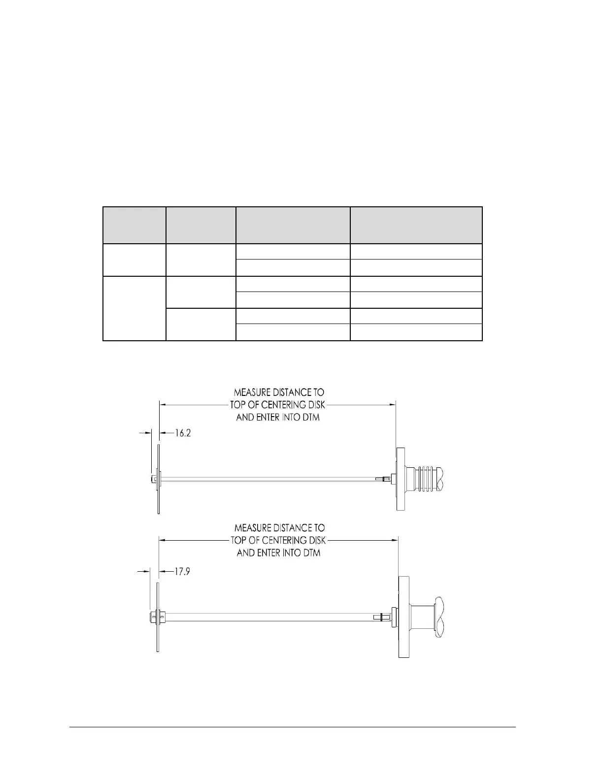
When a centering disk is added to a rod probe, a new probe length must be measured and configured
in the transmitter. Failure to adjust the probe length and the probe termination configurations may
lead to inaccurate readings close to the end of probe or/and may require the user to increase the
blocking distance low. When using a centering disk with a rod probe, the probe length is defined as
the distance from the flange (reference plane) to the top of the disk as shown in Figure 3-20: Probe
length definition for rod probes using a centering disk. When using a wire probe, the probe length is
independent of whether a centering disk is present or not as the probe length is defined as the distance
from the flange (reference plane) to the top of the end weight.
Table 3-14: Probe length for different probe types
MODEL
KEY
PROCESS
CONNECTION
TYPE
PROBE TYPE
LENGTH ENTERED INTO
TRANSMITTER SOFTWARE
SLG 720
Flanged and
Threaded
Rod and coaxial probes
L
Wire probes
L - 150mm
SLG726
Flanged
Rod and coaxial probes
L
Wire probes
L - 150mm
Threaded
Rod and coaxial probes
L + 25mm
Wire probes
L - 125mm
Note: "L" is the probe length specified in the transmitter model number

Table of Contents

Questions and Answers:

Question and Answer IconNeed help?

Do you have a question about the Honeywell SmartLine SLG 700 and is the answer not in the manual?

Honeywell SmartLine SLG 700 Specifications

General IconGeneral
BrandHoneywell
ModelSmartLine SLG 700
CategoryTransmitter
LanguageEnglish

Related product manuals