Revision 8 SLG 700 SmartLine Level Transmitter User’s Manual Page 149
Figure 5-14 - Drill Hole Position on Outer Tube
Step – 7: Reassemble the rod probe. Tighten each rod connection to 6.0 Nm (4.4 ft-lbs).
Step – 8: Reassemble the outer coaxial tube. Tighten each tube segment to 30 Nm (22 ft-lbs),
replacing the M3 set screws into the coaxial tube couplers as required. Tighten M3 set screws to
1.0 Nm (8.8 in-lbs).
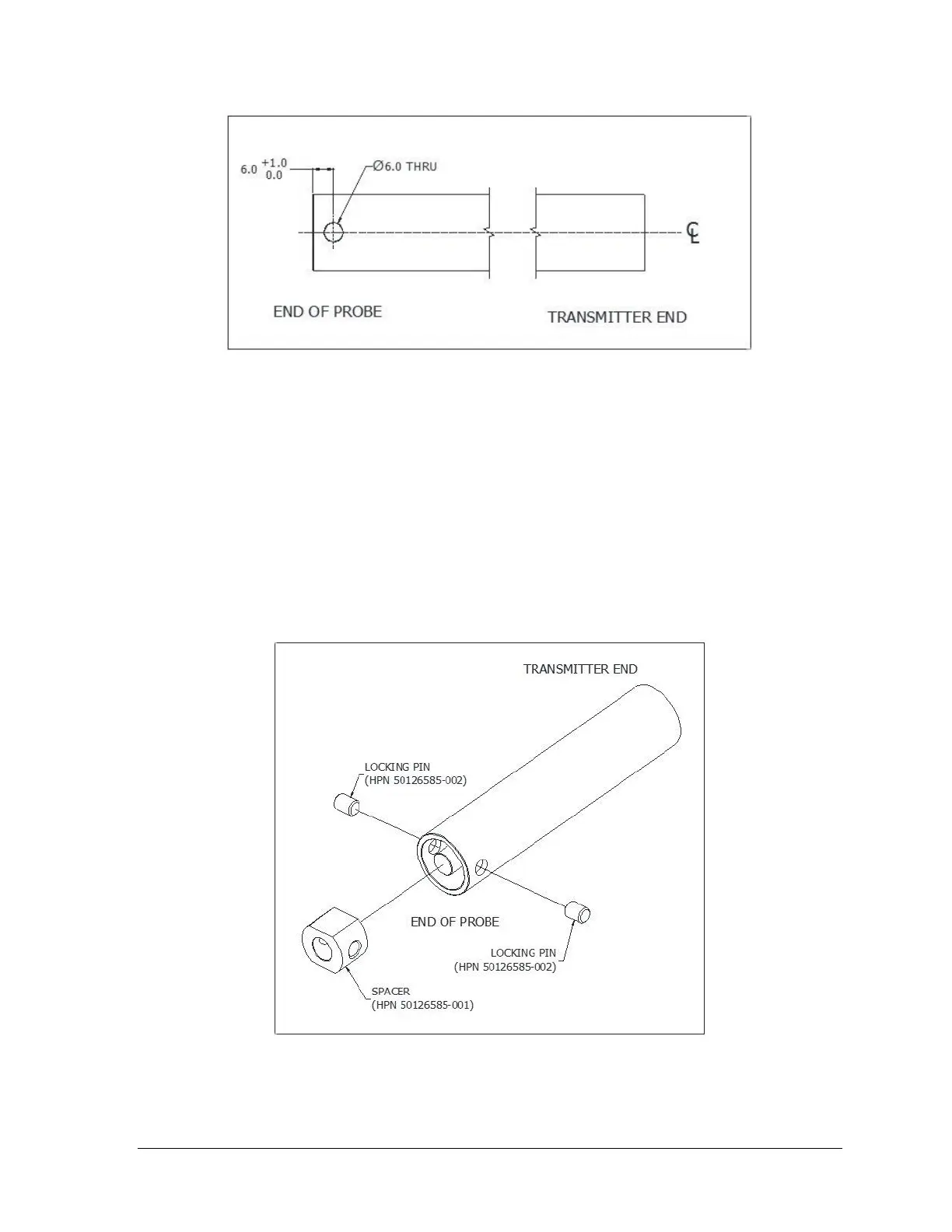
Step – 9: Insert the new spacer (HPN 50126585-001) provided by the Coaxial Probe Trimming Kit
(HPN 50125208) into the end of tube. Align the holes in the end spacer with the newly drilled
holes in the outer tube and insert the two pins (HPN 50126585-002) provided by the Coaxial
Probe Trimming Kit. Refer to Figure 5-15.
Step – 10: Re-configure the probe length in sensor setup according to the SLG700 User's Manual
34-SL-25-11.
Figure 5-15 - Spacer and Locking Pin Installation

 Loading...


