Revision 8 SLG 700 SmartLine Level Transmitter User’s Manual Page 49
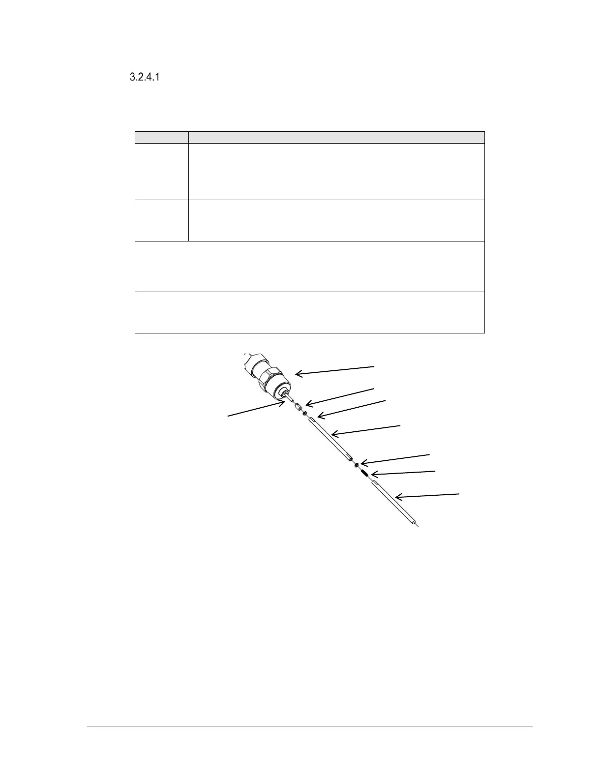
Rod probe assembly
Rod probes are shipped in segments. The segments are attached to each other with a stud
and a lock washer.
Fully thread the nut onto the central conductor. Using a lock
washer, thread the first rod segment on to the central conductor.
Torque the nut against rod probe and lock washer to secure the
connection.
Thread the stud into first rod segment end. Using a lock washer
thread the next segment onto the stud. Apply torque to secure
the connection.
Note: Tighten each rod connection point to the following torques:
SLG720 6.0Nm (4.4ft-lbs)
SLG726 15Nm (11ft-lbs)
Note: For flanged SLG726 models, ensure the nut does not intrude into the
process connector. See Error! Reference source not found. for more
information.
Figure 3-9: Rod probe assembly

 Loading...


