Revision 8 SLG 700 SmartLine Level Transmitter User’s Manual Page 59
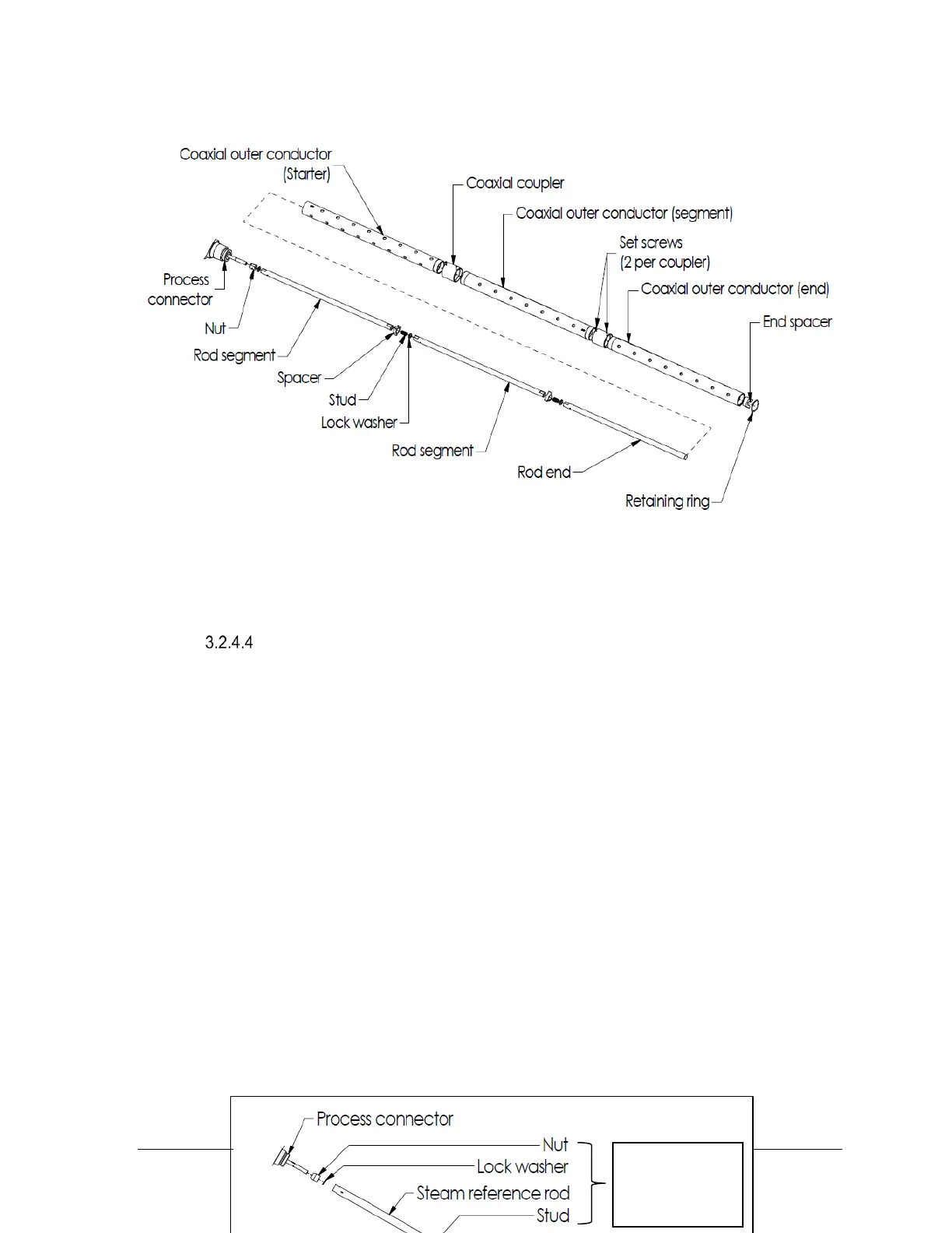
Figure 3-14: SLG726 Coaxial probe assembly
(Segmented outer tube depicted)
Saturated Steam Application Probe Assembly
Saturated steam application is available with SLG726 rod and coax probes. The nut and first inner rod
segment have a larger diameter. The remaining hardware is identical. Refer to Error! Reference
source not found. for saturated steam hardware. To assemble the probes, thread the saturated steam
application nut to the central conductor, tapered end towards the process connector. For flanged
process connectors, ensure the nut position is as shown in Figure 3-10: SLG726 flanged process
connection, probe nut installation position, mm [in]. Place a lock washer between the locknut and the
steam reference rod. Torque the connection to 15Nm (11ft-lbs). Proceed with the standard assembly
procedures detailed above.
Saturated
steam

 Loading...


