EasyManuals Logo

Honeywell SmartLine SLG 700 User Manual

Honeywell SmartLine SLG 700
198 pages
To Next Page IconTo Next Page
To Previous Page IconTo Previous Page
Page #89 background imageLoading...
Page #89 background image
Revision 8 SLG 700 SmartLine Level Transmitter User’s Manual Page 73
Suitable mounting position
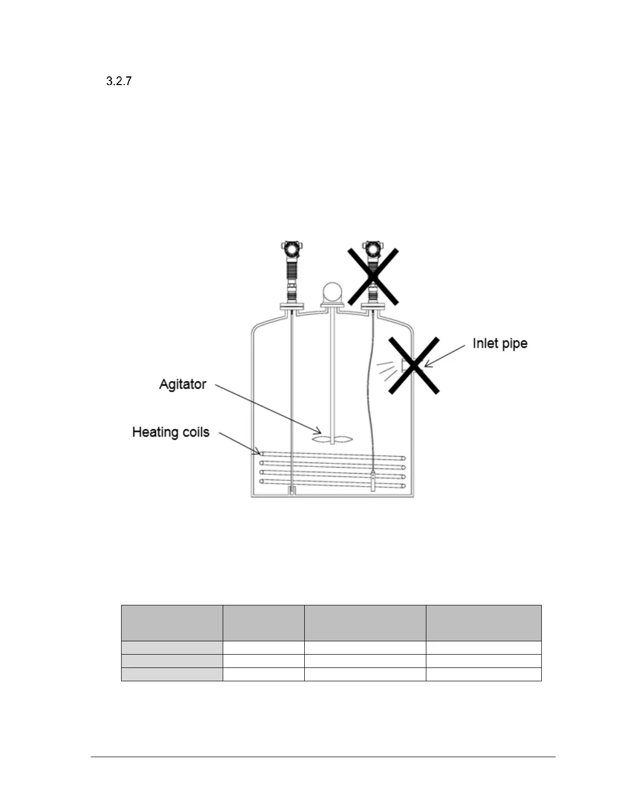
To minimize signal interference, observe the minimum distances in Table 3-15.
Examples of obstacles to avoid are protruding welds, internal installations, agitators,
pipes and nozzles extending into the container, heating coils, inlet streams, ladders, etc.
Metallic objects are a source of bigger interferences than non-metallic objects.
Turbulent applications may require the probe to be anchored to prevent it from contacting
or getting too close to container walls or obstacles.
Figure 3-27: Mounting position
Table 3-15: Minimum recommended distance to container wall and obstacles (mm)
Probe
Minimum
distance to
obstacle
Minimum distance to
metallic container
wall
Minimum distance
to non-metallic
container wall
Single wire
500mm (20″)
100mm (4″)
500mm (20″)
Single rod
500mm (20″)
100mm (4″)
500mm (20″)
Coax
0mm (0″)
0mm (0″)
0mm (0″)

Table of Contents

Questions and Answers:

Question and Answer IconNeed help?

Do you have a question about the Honeywell SmartLine SLG 700 and is the answer not in the manual?

Honeywell SmartLine SLG 700 Specifications

General IconGeneral
BrandHoneywell
ModelSmartLine SLG 700
CategoryTransmitter
LanguageEnglish

Related product manuals