Page 144 SLG 700 SmartLine Level Transmitter User’s Manual Revision 8
Step – 3: Remove existing probe using appropriate wrenches. Remove the existing end-of-
probe hardware if it is needed for the new probe.
Step – 4: Attach new probe
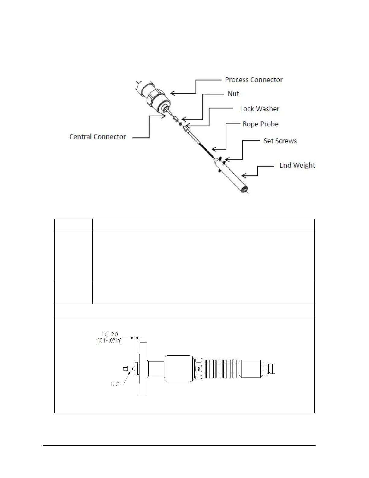
Fully thread the nut onto the central conductor. Using a lock washer, thread the
wire swage on to the central conductor. Torque the nut against probe and lock
washer to secure the connection.
Note:
Tighten the wire stud and nut to the following torque:
- SLG720 6.0 Nm (4.4 ft-lbs)
- SLG726 15 Nm (11 ft-lbs)
If applicable, insert wire probe into end weight. Tighten the 3 set screws to
secure end weight to wire probe.
Note: Torque set screws to 6 Nm (4.4 ft-lbs)
Note: For flanged SLG726 models, ensure the nut does not intrude into the bore of the
process connector. See image below for acceptable spacing.

 Loading...


