4-16
Assembly
Access
To remove I/O
card
from controller assembly:
1.
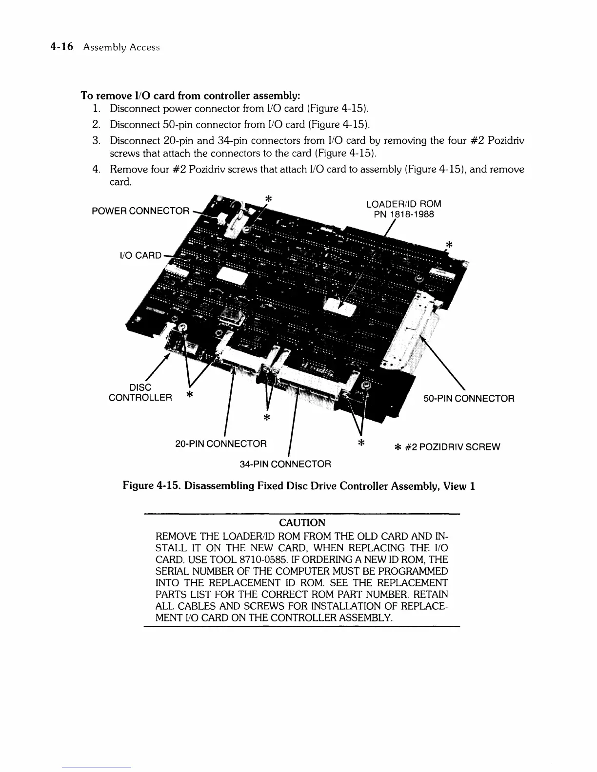
Disconnect power connector from I/O card (Figure 4-15).
2.
Disconnect 50-pin connector from I/O card (Figure 4-15).
3. Disconnect 20-pin
and
34-pin connectors from I/O card by removing the four
#2
Pozidriv
screws that attach the connectors to the card (Figure 4-15).
4.
Remove four
#2
Pozidriv screws that attach I/O card to assembly (Figure 4-15),
and
remove
card.
POWER CONNECTOR
DISC
CONTROLLER
34-PIN CONNECTOR
50-PIN CONNECTOR
*
#2
POZIDRIV SCREW
Figure 4-15. Disassembling Fixed Disc Drive Controller Assembly, View 1
CAUTION
REMOVE THE LOADERIID ROM FROM THE OLD CARD AND IN-
STALL
IT ON THE NEW CARD, WHEN REPLACING THE 1/0
CARD.
USE
TOOL 8710-0585.
IF
ORDERING A NEW 10
ROM,
THE
SERIAL
NUMBER
OF
THE COMPUTER MUST
BE
PROGRAMMED
INTO
THE REPLACEMENT 10
ROM.
SEE
THE REPLACEMENT
PARTS
LIST FOR THE CORRECT ROM PART NUMBER. RETAIN
ALL
CABLES AND SCREWS
FOR
INSTALLATION
OF
REPLACE-
MENT
110
CARD ON THE CONTROLLER ASSEMBLY.