Chapter 7
Removing and Replacing Components
Processors
164
CAUTION When rotating the locking cam, hold the palm of your hand on top of the assembly and exert light
pressure. This ensures that the assembly stays flush and level to the socket while it is being
tightened.
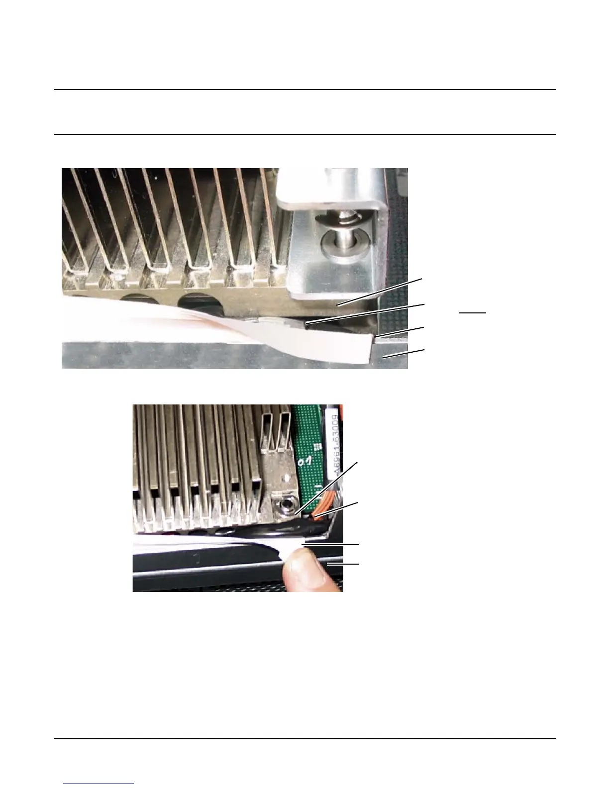
Figure 7-13 Processor Cable Placed Correctly
Figure 7-14 Processor Cable Placed Incorrectly
Step 9. Plug in the processor cable to its socket on the extender board.
Step 10. Place the sequencer frame over the processor.
Step 11. Using the supplied torx T15 driver, tighten the 6 T15 shoulder screws until they just bottom out. Follow the
tightening sequence shown in Figure 7-15, “Installing Processor on Extender Board.”
Heatsink
Cable is placed correctly
and is under
the heatsink
Protective plastic sleeve
Sheetmetal frame
Heatsink
Cable is placed
incorrectly and is
pinched between the
heatsink and the
extender board frame
Protective plastic sleeve
Sheetmetal frame