Chapter 7
Removing and Replacing Components
I/O Baseboard Assembly
174
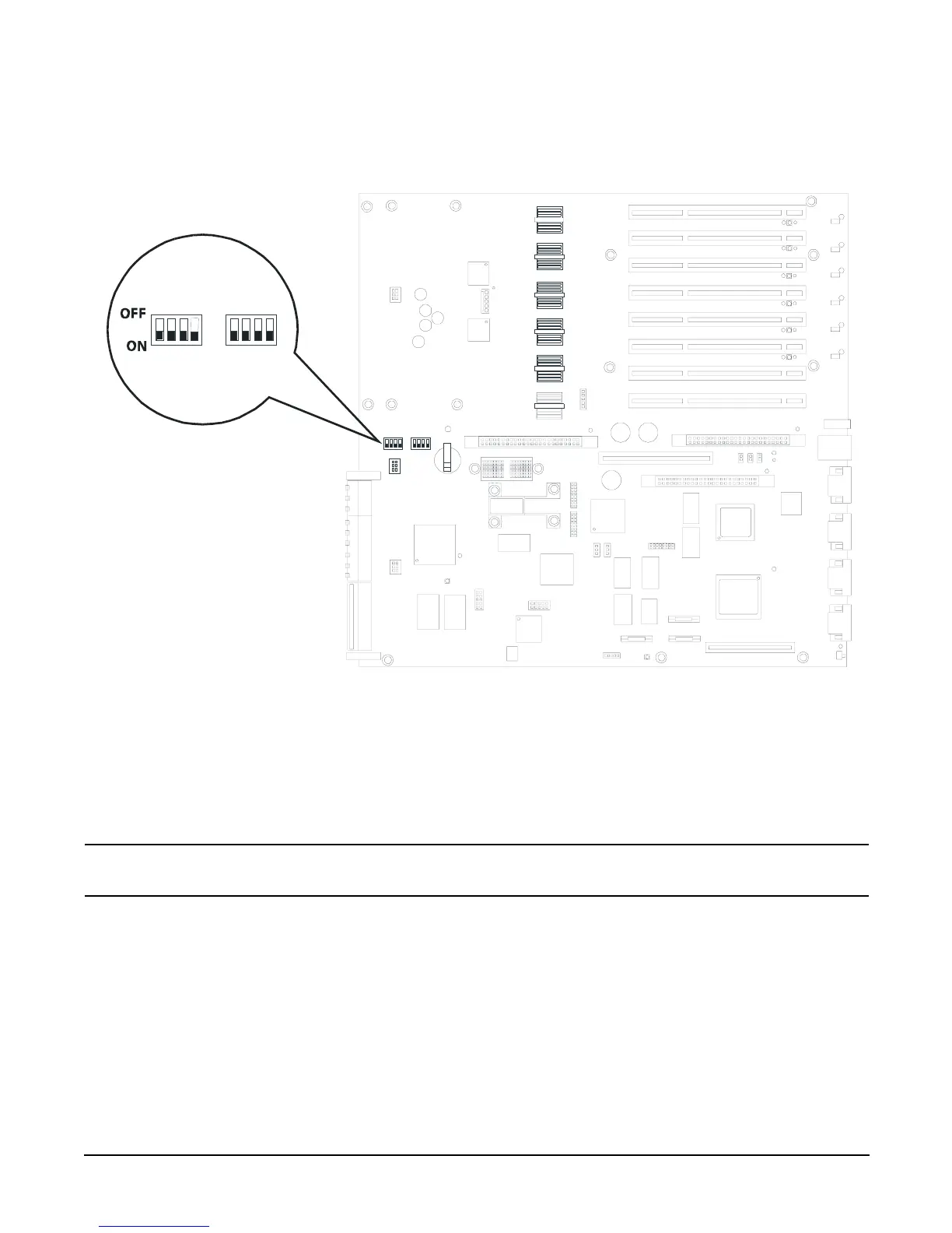
Step 1. Set the I/O baseboard select switches as shown in
Figure 7-20I/O Baseboard Select Switches
Step 2. Align the I/O baseboard assembly rails with the chassis slots and slide the assembly into the chassis until it stops
against the midplane riser board socket.
CAUTION Ensure the I/O board locking lever is in the “up” position or the I/O board will hang up before
engaging the midplane riser board socket.
Step 3. With the I/O board flush against the midplane riser board socket, push down firmly on the locking lever until the
I/O baseboard plugs all the way into the midplane riser board socket.
Step 4. Replace the three chassis fan units.
Step 5. Plug in all external cabling the rear ports of the I/O baseboard.
Select switches